
Film bridge assembly for a digital film scanning system

a technology of digital film scanning and film bridge, which is applied in the field of film bridge, can solve the problems of reducing affecting the quality of scanned images, and inferior digital images

Inactive Publication Date: 2006-01-26
EASTMAN KODAK CO
View PDF2 Cites 0 Cited by
  • Summary
  • Abstract
  • Description
  • Claims
  • Application Information

AI Technical Summary

Benefits of technology

[0009] The present invention relates to a method and apparatus in which the magnitude and frequency of defects that are applied to the film during film transportation and scanning are reduced. More specifically, the invention provides for a film bridge design that reduces or eliminates film scratching and reduces the susceptibility of film to debris to prevent defects to the image.
[0010] The present invention further provides for a film bridge that is adapted to maintain the film in a flat state at a constant height, while at the same time permitting the application of a desired illumination intensity through the film.

Problems solved by technology

In addition, the mechanisms used to transport and control the position of the film during scanning should avoid imparting scratches or other physical defects to the image area of the film, as such scratches and defects can result in an inferior digital image.
First, pulling film across a metallic or plastic material tends to induce scratches that reduce scanned image quality.
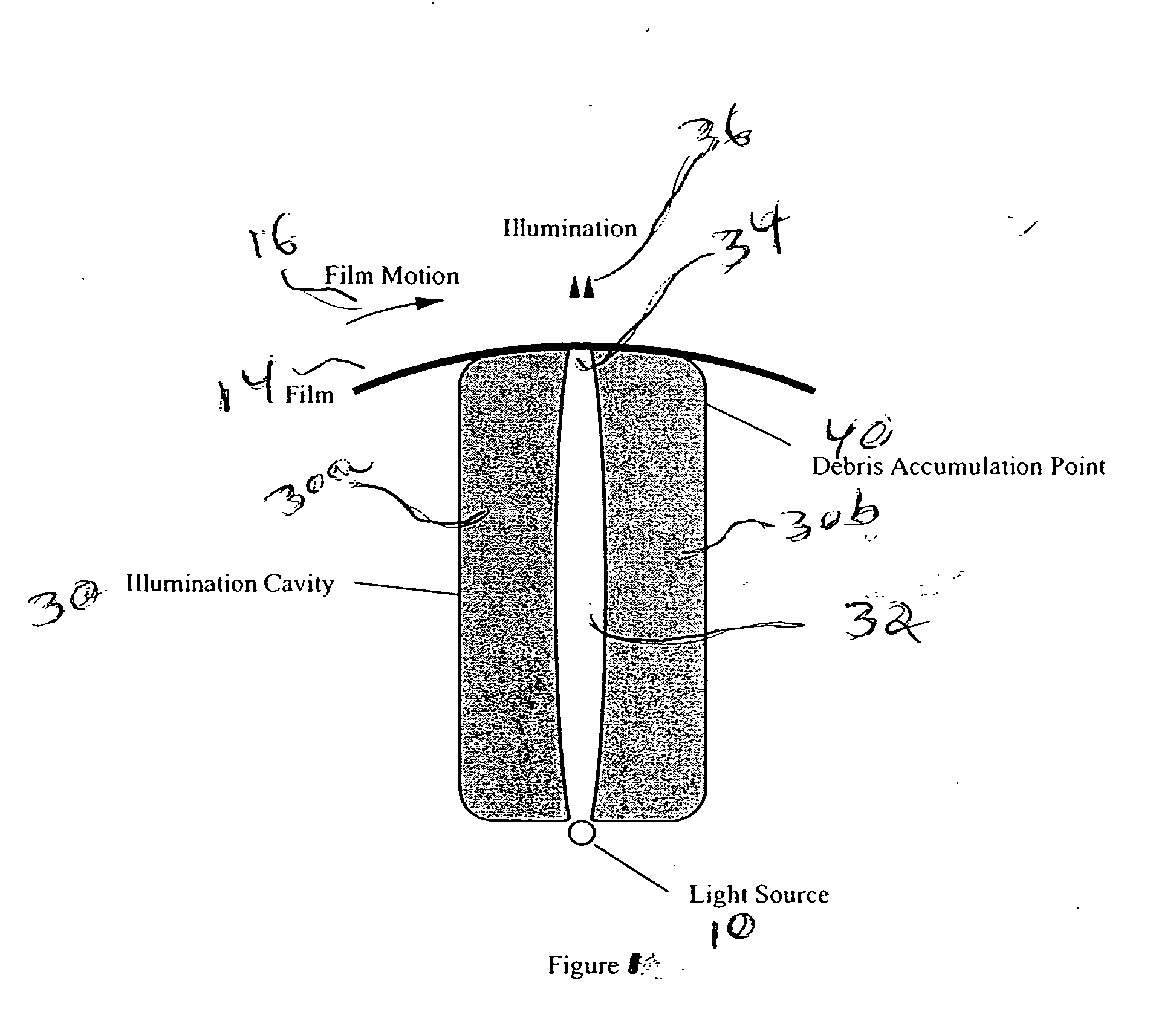
The debris from the scratches and other areas of the machine also tends to get trapped on an area of the trailing edge of the slot (shown in general by reference numeral 40 in FIG. 1) that also causes scanning problems.
The scratching is lessened when the film tension is reduced but this causes flatness and focus irregularities with the film that leads to poor image quality.

Method used


Image

  • Film bridge assembly for a digital film scanning system
  • Film bridge assembly for a digital film scanning system
  • Film bridge assembly for a digital film scanning system

Examples


Embodiment Construction

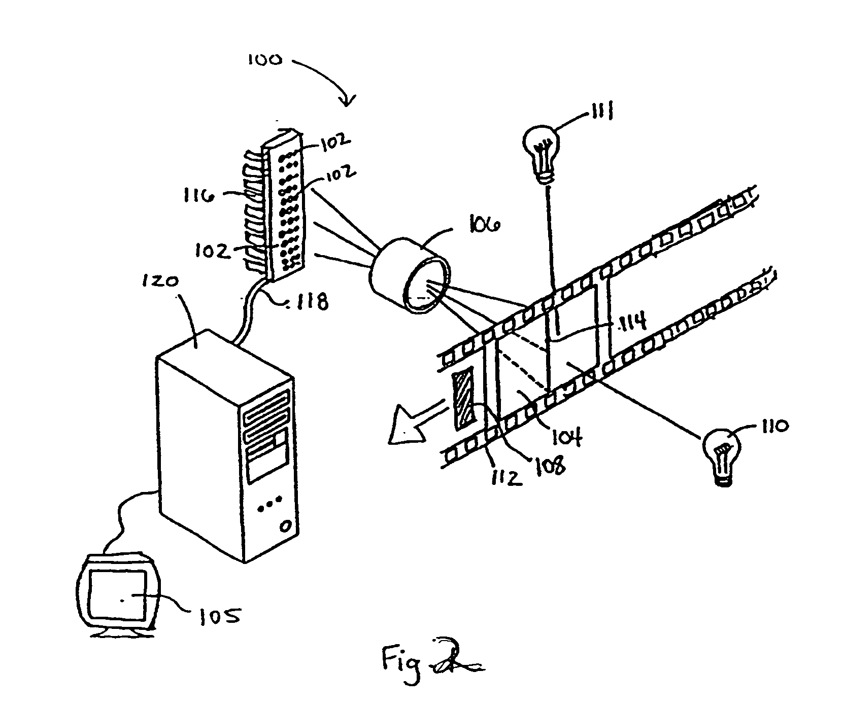
[0024] Referring now to the drawings, wherein like reference numerals represent identical or corresponding parts throughout the several views, FIG. 2 shows an exemplary digital film processing system (DFP) 100. The system operates by converting electromagnetic radiation from an image to an electronic (digital) representation of the image. The image being scanned is typically provided on a photographic film media 112 that is being developed using chemical developer. In some applications, the electromagnetic radiation used to convert the image into a digital representation is infrared light; however, visible light, microwave and other suitable types of electromagnetic radiation may also be used to produce the digitized image. The scanning system 100 generally includes a number of optic sensors 102, which measure the intensity of electromagnetic energy passing through or reflected by the developing film 112. The source of electromagnetic energy is typically a light source 110 that illu...


PUM


Abstract

A film bridge assembly adapted to precisely position film during scanning in a digital film processing system. The film bridge assembly makes up part of a film bridge and illuminator cavity system that includes a slot for the passage of illumination light that is used to scan film at an opening of the slot. A window or cylindrical lens is provided at the opening of the slot to permit film to pass over the slot without incurring any scratching. The window or lens is effective to keep the film at a constant height, reduce debris at the image plane, and permit a maximum amount of illumination light to pass through the film.

Description

FIELD OF THE INVENTION [0001] The present invention relates generally to film scanning, and more particularly to a film bridge for use in the transportation and scanning of film in a film scanning system. BACKGROUND OF THE INVENTION [0002] Color photographic film generally comprises three layers of light sensitive material that are separately sensitive to red, green, and blue light. During conventional color photographic film development, the exposed film is chemically processed to produce dyes in the three layers with color densities directly proportional to the blue, green and red spectral exposures that were recorded on the film in response to the light reflecting from the photographed scene. Yellow dye is produced in the top layer, magenta dye in the middle layer, and cyan dye in the bottom layer, the combination of the produced dyes revealing the latent image. Once the film is developed, a separate printing process can be used to record photographic prints, using the developed ...

Claims


Application Information

Patent Timeline
IPC IPC(8): H04N1/23
CPCH04N1/00909H04N1/121H04N2201/0456H04N3/38H04N2201/0408H04N1/193
Inventor MCPEAK, JASONDUONG, DUNG T.MAPEL, WILLIAM D.
Owner EASTMAN KODAK CO
Learn More