
Levitation rig

a technology of levitation rig and rotor, which is applied in the direction of mechanical equipment, magnetic bearings, instruments, etc., can solve the problems of impracticality, conventional carrier systems such as wheels, and inconvenient us

Active Publication Date: 2017-04-20
HYPERLOOP TECH INC
View PDF9 Cites 0 Cited by
  • Summary
  • Abstract
  • Description
  • Claims
  • Application Information

AI Technical Summary

Benefits of technology

The patent text describes a new invention and its features. The invention is not limited to the specific features described in the patent, and there may be other features not described in the text. The technical effect of the invention is that it allows for flexibility in design and modification without restricting or limiting the invention to specific features. The patent explains that the invention includes all such alterations, modifications, and variations that are within the scope of the patent.

Problems solved by technology

However, the adverse environmental, societal and economic impacts of these traditional transportation models initiated a movement to find alternative transportation modes that take advantage of the significant improvements in transportation technology and efficiently move people and materials between locations.
Frictional forces resulting from the high operating speeds of the vehicle render conventional carrier systems, such as wheels, impractical.

Method used


Image

  • Levitation rig
  • Levitation rig
  • Levitation rig

Examples


Embodiment Construction

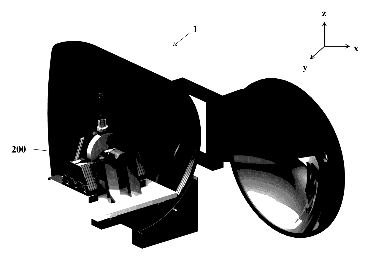
[0006]A testing apparatus includes a chamber having an interior maintained at a predetermined pressure, a rotor disposed within the interior of the chamber and configured to rotate within the chamber; and at least one sensor disposed within the interior of the chamber, wherein when the rotor rotates, the at least one sensor is configured to measure a testing characteristic of an object disposed within the interior of the chamber as the object interacts with the rotating rotor.

[0007]The predetermined pressure of the interior may be lower than 1 atmosphere, or lower even than 0.001 atmosphere. The predetermined pressure may be a pressure between 0.001 atmosphere and 1 atmosphere. The predetermined pressure may be a pressure between 0.006 atmosphere and 0.018 atmosphere.

[0008]The rotor may be configured to rotate to achieve a surface speed that exceeds 300 meters per second (m / s).

[0009]The testing characteristic of the object may be at least one of lift, drag, temperature, pressure, an...


PUM


Abstract

A testing apparatus includes a chamber, having an interior maintained at a predetermined pressure, a rotor rotatably disposed within the interior of the chamber, and a sensor disposed within the interior of the chamber. When the rotor rotates, the at least one sensor measures a testing characteristic of an object disposed within the interior of the chamber as the object interacts with the rotating rotor. A method includes setting a predetermined pressure of a chamber, rotating a rotor, and maintaining a gap between a surface of an object to be tested and a surface of the rotor by adjusting, with an actuator, the object to be tested or the rotor based upon a change, as measured by a laser, in the dimension of the object to be tested or the rotor.

Description

CROSS REFERENCE TO RELATED APPLICATION[0001]The present application claims the benefits of U.S. Provisional Application No. 62 / 243,875 filed on Oct. 20, 2015, the disclosure of which is expressly incorporated by reference herein in its entirety.FIELD OF THE DISCLOSURE[0002]The present disclosure relates a testing apparatus including a chamber having an interior maintained at a pressure and a rotor disposed within the interior of the chamber, and a method for maintaining a gap between a surface of a bearing and a surface of a rotor disposed within a chamber maintained at a pressure.BACKGROUND OF THE DISCLOSURE[0003]Traditional transportation modes via water, land, rail and air revolutionized the movement and growth of our current culture. However, the adverse environmental, societal and economic impacts of these traditional transportation models initiated a movement to find alternative transportation modes that take advantage of the significant improvements in transportation technolo...

Claims


Application Information

Patent Timeline
Patent Type & Authority Applications(United States)
IPC IPC(8): G01M13/04G01M9/04
CPCG01M13/04G01M9/04F16C2300/22F16C32/0603F16C2300/62F16C32/0406
Inventor FERM, JETTCOUTRE, JAMESOKERSON, RYANMERCURY, CASSANDRADEHAAN, DAVID
Owner HYPERLOOP TECH INC
Learn More