
Suspension assembly having reinforced end-tab and actuator for disk drive adopting the same

a technology of end-tab and actuator, which is applied in the direction of instruments, breathing protection, data recording, etc., can solve the problems of inability to perform its own function, damage to the head and/or the disk, and long time for unloading the end-tab, etc., to increase the data storage space of the disk, increase the vertical and horizontal stiffness of the end-tab

Inactive Publication Date: 2006-01-19
SAMSUNG ELECTRONICS CO LTD
View PDF14 Cites 13 Cited by
  • Summary
  • Abstract
  • Description
  • Claims
  • Application Information

AI Technical Summary

Benefits of technology

[0025] The present invention provides a suspension assembly and an actuator for a disk drive adopting the same, which are capable of increasing vertical and horizontal stiffness of an end-tab and increasing data storage space of a disk.
[0026] According to an aspect of the present invention, there is provided a suspension assembly of an actuator for a disk drive, which elastically biases a slider toward a surface of a disk, a read / write head being mounted on the slider. The suspension assembly comprises: a load beam coupled to a first portion of a swing arm of the actuator; a flexure that supports the slider, the flexure having a first end portion fixed to a disk facing surface of the load beam and a second end portion extended toward a first end portion of the load beam; and an end-tab extended from the first end portion of the load beam, the end-tab being supported by a ramp arranged in an outside of the disk when the head is parked, wherein the end-tab is deflected from a longitudinal central axis of the load beam toward the outside of the disk while extending from the first end portion of the load beam, thereby increasing both vertical and horizontal stiffness of the end-tab.
[0030] According to another aspect of the present invention, there is provided an actuator for a disk drive, comprising: a swing arm pivotally mounted on a base member of the disk drive; a suspension assembly elastically biasing a slider toward a surface of a disk, a read / write head to reproduce / record data being mounted on the slider; and a voice coil motor that rotates the swing arm to move the read / write head to a predetermined position of the disk. The suspension assembly comprises: a load beam coupled to a first portion of the swing arm of the actuator; a flexure that supports the slider, the flexure having a first end portion fixed to a disk facing surface of the load beam and a second end portion extended toward a first end portion of the load beam; and an end-tab extended from the first end portion of the load beam, the end-tab being supported by a ramp arranged in an outside of the disk when the head is parked, wherein the end-tab is deflected from a longitudinal central axis of the load beam toward the outside of the disk while extending from the first end portion of the load beam, thereby increasing both vertical and horizontal stiffness of the end-tab.
[0031] Compared with the related art, both vertical and horizontal stiffness of the end-tab are increased, and an overlapped width between the ramp and the disk is reduced, resulting in increased data storage space of the disk.

Problems solved by technology

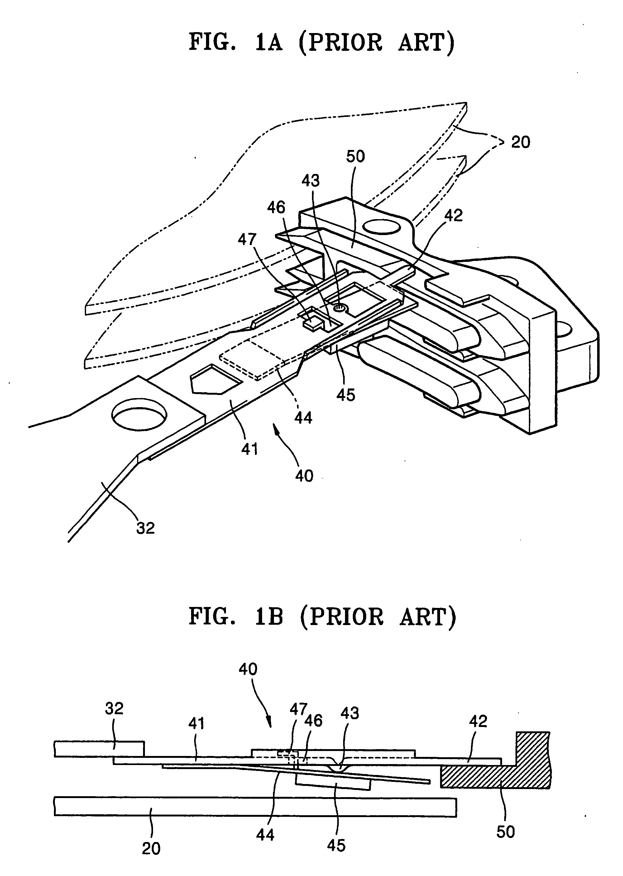
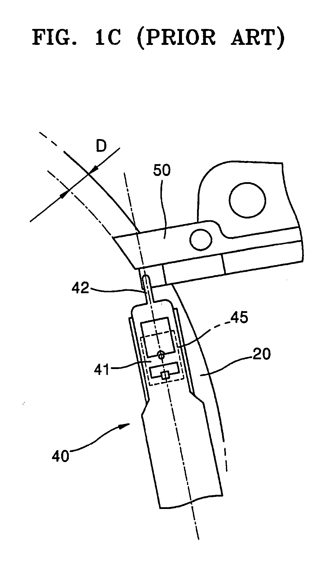
If this phenomenon occurs, the limiter 47 cannot perform its own function, such that the head and / or the disk 20 may be damaged due to a collision.
In addition, when stiffness of the end-tab 42 is low, it takes a long time to unload the end-tab 42.
Compared with the end-tab of FIG. 1A, the end-tab of FIGS. 2A through 2C has an effect that increases the vertical stiffness, but does not have a satisfactory effect in the horizontal stiffness and the overlapped width between the ramp and the disk.
This end-tab has an advantage in that an overlapped width between the ramp and the disk is reduced, but has a disadvantage in that stiffness of the end-tab is insufficient and a twist deformation occurs.

Method used


Image

  • Suspension assembly having reinforced end-tab and actuator for disk drive adopting the same
  • Suspension assembly having reinforced end-tab and actuator for disk drive adopting the same
  • Suspension assembly having reinforced end-tab and actuator for disk drive adopting the same

Examples


Embodiment Construction

[0047] Reference will now be made in detail to embodiments of the present invention, examples of which are illustrated in the accompanying drawings, wherein like reference numerals refer to the like elements throughout. The embodiments are described to explain the present invention by referring to the figures.

[0048] In the drawings, the thickness of layers and regions are exaggerated for clarity.

[0049]FIG. 3 is a plan view schematically illustrating a structure of a hard disk drive, which adopts a suspension assembly of an actuator according to an embodiment of the present invention.

[0050] Referring to FIG. 3, the hard disk drive includes: a spindle motor 112 mounted on a base member 110; one or more disks 120 fixedly installed in the spindle motor 112; and an actuator 130 moving a read / write head (not shown) to a predetermined position of the disk 120. Here, the read / write head is a device to reproduce / record data from / on the disk 120.

[0051] The actuator 130 includes: a swing a...


PUM

PropertyMeasurementUnit
stressaaaaaaaaaa
thicknessaaaaaaaaaa
thickaaaaaaaaaa

Abstract

A suspension assembly elastically biasing a slider toward a surface of a disk, in which a read / write head is mounted on the slider. In the suspension assembly, a load beam is coupled to a first portion of a swing arm of the actuator. A flexure supports the slider and has a first end portion fixed to a disk facing surface of the load beam and a second end portion extended toward a first end portion of the load beam. An end-tab is extended from the first end portion of the load beam. When the head is parked, the end-tab is supported by a ramp, which is arranged at an outside of the disk.

Description

CROSS-REFERENCE TO RELATED APPLICATIONS [0001] This application claims the priority of Korean Patent Application No. 2004-3802, filed on Jan. 19, 2004, in the Korean Intellectual Property Office, the disclosure of which is incorporated herein by reference. BACKGROUND OF THE INVENTION [0002] 1. Field of the Invention [0003] The present invention relates to a disk drive, and more particularly, to a suspension assembly having an end-tab, a stiffness of which is reinforced, and an actuator for a disk drive adopting the same. [0004] 2. Description of the Related Art [0005] As an information storage device of computer, a hard disk drive (HDD) is a device to reproduce / record data from / on disk using a read / write head. [0006] Such a hard disk drive includes an actuator moving a read / write head to a predetermined position of a disk. The actuator is provided with: a swing arm; a suspension assembly installed in one end portion of the swing arm to elastically bias a slider toward a surface of t...

Claims


Application Information

Patent Timeline
Patent Type & Authority Applications(United States)
IPC IPC(8): G11B5/48G11B5/54G11B21/22G11B21/12G11B21/21
CPCG11B21/22G11B5/54A62B23/00
Inventor CHOI, BYOUNG-GYOUKIM, JEONG-SEONSHIM, DONG-LOUVALERI, TOHAMINKVALERY, KRASNOSTOODTSEV
Owner SAMSUNG ELECTRONICS CO LTD
Learn More