
Liquid crystal display device manufacturing method and liquid crystal display device manufacturing system

a liquid crystal display device and manufacturing method technology, applied in the direction of ceramic shaping apparatus, instruments, optics, etc., can solve the problems of lowering the discharge precision of liquid crystal under such conditions, trouble on the display, and lowering the precision of liquid crystal discharge. , to achieve the effect of reducing the error of liquid crystal amount in the excellent display of liquid crystal display device, and high precision

Inactive Publication Date: 2006-01-19
SHARP KK
View PDF6 Cites 0 Cited by
  • Summary
  • Abstract
  • Description
  • Claims
  • Application Information

AI Technical Summary

Benefits of technology

[0015] It is an object of the present invention to provide a liquid crystal display device manufacturing method and a liquid crystal display device manufacturing system capable of supplying an amount of the liquid crystal to a substrate with high precision.
[0017] Accordingly, because the liquid crystal adhered to the liquid crystal supply needle is dropped by the external force to supply onto the substrate, such liquid crystal can be supplied onto the substrate by a high precision amount and thus the display of the liquid crystal display device becomes excellent.
[0018] Also, the above subject can be overcome by replenishing the liquid crystal into the syringe from the outside by the same defined amount as the liquid crystal dropped from the syringe such that the pushing force of the liquid crystal to the liquid crystal supply needle can be maintained constant and that the liquid crystal can be dropped from the liquid crystal supply needle at the speed not to left the liquid crystal on the surface of the liquid crystal supply needle of the syringe.
[0019] Accordingly, the liquid crystal is not left on the surface of the liquid crystal supply needle, and also the variation of the drop conditions of the liquid crystal can be suppressed because the drop of the liquid crystal by the same amount in the syringe can be started. As a result, the error of the liquid crystal amount in the liquid crystal display device can be reduced, and also the defective display of the liquid crystal display device can be reduced.

Problems solved by technology

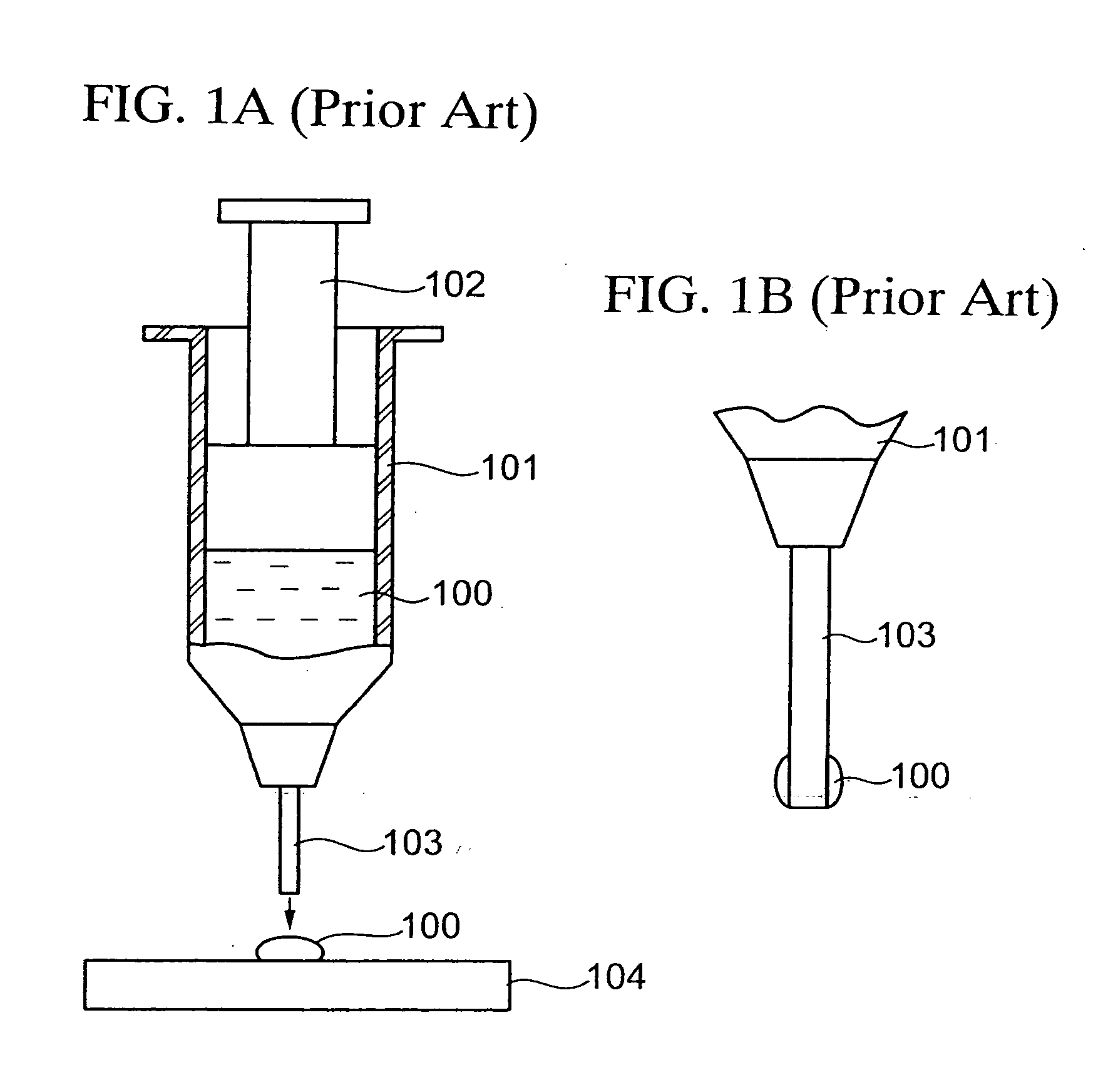
If the adhered liquid crystal remains at the top of the needle, the precision in supplying the liquid crystal to the cell is lowered and thus the trouble occurs on the display.
In this case, there is such a disadvantage that the discharge precision of the liquid crystal is lowered under such condition.

Method used


Image

  • Liquid crystal display device manufacturing method and liquid crystal display device manufacturing system
  • Liquid crystal display device manufacturing method and liquid crystal display device manufacturing system
  • Liquid crystal display device manufacturing method and liquid crystal display device manufacturing system

Examples


first embodiment

[0028] (First Embodiment)

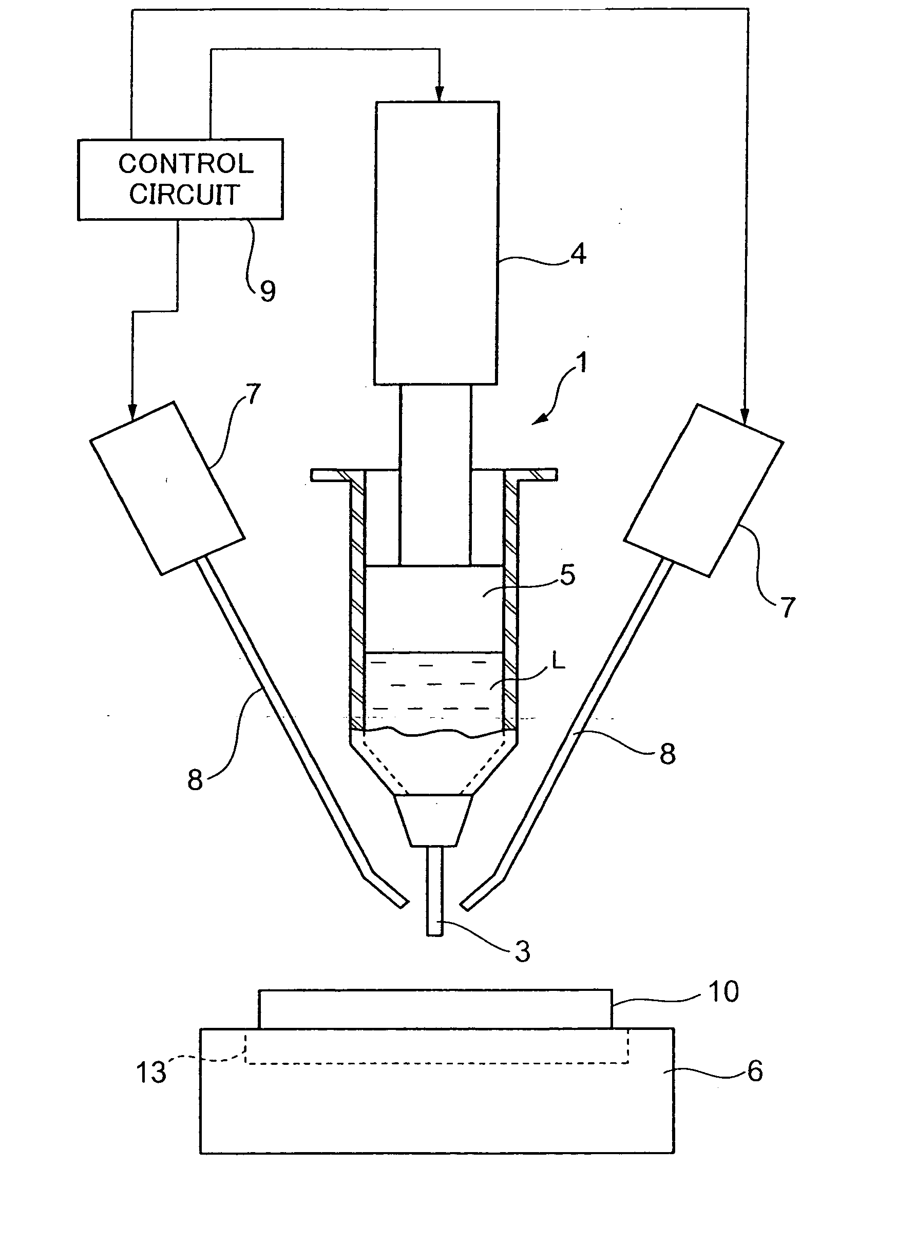
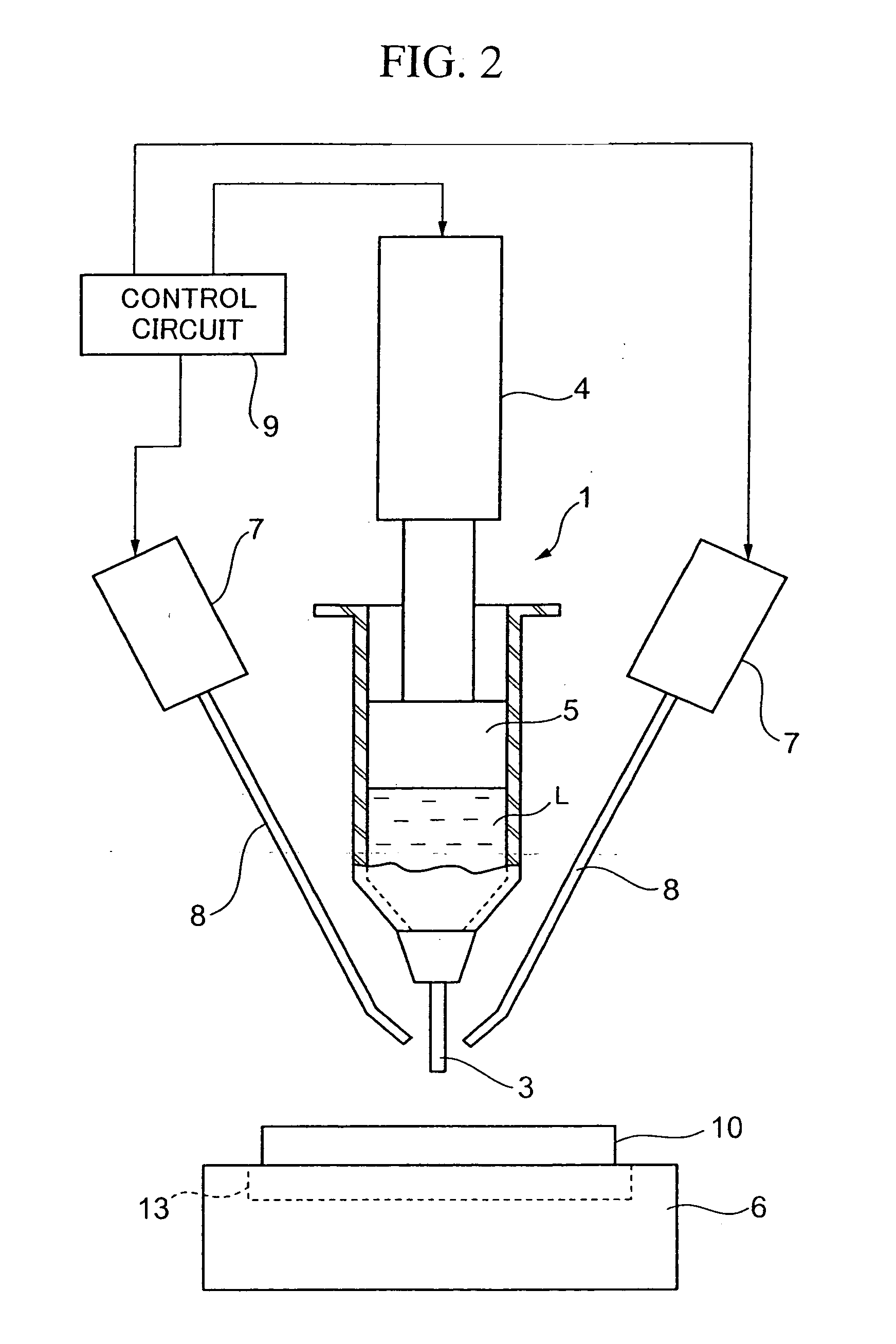
[0029]FIG. 2 is a view showing a configuration of a liquid crystal supplying equipment employed to manufacture a liquid crystal display device according to a first embodiment of the present invention.

[0030] In FIG. 2, a hollow liquid crystal supply needle 3 is provided to the bottom end of a liquid crystal supply syringe 1 to drop down the liquid crystal L in the syringe 1 on a first substrate 10. A plunger 5 that is connected to a driving source 4 is inserted into the inside of the syringe 1, and the liquid crystal L is pushed out from the top end of the liquid crystal supply needle 3 by descending the plunger 5. The plunger 5 is mechanically moved vertically by the driving source 4.

[0031] A loading table 6 on which the first substrate 10 is loaded is arranged movably under the syringe 1. Also, the syringe 1 is arranged at a height, that provides an interval of 10 to 20 mm, for example, between the loading table 6 and the liquid crystal supply needle 3, s...

second embodiment

[0056] (Second Embodiment)

[0057] The plunger system syringe is employed as the liquid crystal supplying equipment shown in FIG. 2, but an air system syringe 15 shown in FIG. 6 may be employed. In the case of this air system syringe, the air supply needles 8 may also be arranged around the liquid crystal supply needle. In this air system syringe 15, the liquid crystal can be dropped down from a liquid crystal supply needle 17 provided to the top end of the syringe 15 by pressuring the liquid crystal filled in the syringe 15 from the upper side by the air pressure.

[0058] According to the air system plunger, even if the same air pressure is applied to the inside of the syringe 15, a total amount of the liquid crystal dropped onto the first substrate 10 is varied because of a residual amount of the liquid crystal in the syringe 15, as shown in Table 3. Table 3 shows the cases where an amount of the liquid crystal in the syringe 15 is set to 15 g (large), 7 g (middle), and 2.5 g (small)...


PUM

PropertyMeasurementUnit
heightaaaaaaaaaa
specific gravityaaaaaaaaaa
areaaaaaaaaaaa

Abstract

There is provided a liquid crystal display device manufacturing method that comprises the steps of forming a sealing member along a periphery of a display area on a first surface of a first substrate, dropping a liquid crystal to the first surface of the first substrate from a top end of a liquid crystal supply needle provided to a lower end of a syringe in which the liquid crystal is filled, and dropping down the liquid crystal adhered to a surface of the liquid crystal supply needle onto the first substrate by an external force in a middle of dropping of the liquid crystal or after the liquid crystal is dropped. Accordingly, an amount of liquid crystal supplied to the substrate can be controlled with high precision.

Description

BACKGROUND OF THE INVENTION [0001] 1. Field of the Invention [0002] The present invention relates to a liquid crystal display device manufacturing method and a liquid crystal display device manufacturing system and, more particularly, a liquid crystal display device manufacturing method having the step of dropping a liquid crystal into a substrate from a syringe and a system used to manufacture the liquid crystal display device. [0003] 2. Description of the Prior Art [0004] The liquid crystal display device has a structure that the TFT substrate on which the pixel electrodes, the thin film transistors (TFTs), etc. are formed and the opposed substrate on which the opposed electrode, the color filters, etc. are formed are stuck together, and the liquid crystal sealed between the TFT substrate and the opposed substrate. [0005] As the method of sealing the liquid crystal between the TFT substrate and the opposed substrate, the vacuum injection method, the drop method, etc. are employed....

Claims


Application Information

Patent Timeline
Patent Type & Authority Applications(United States)
IPC IPC(8): B28B1/08G02F1/1341
CPCG02F2001/13415G02F1/1341G02F1/13415
Inventor SUGIMURA, HIROYUKIYUHARA, TAIJIMURATA, SATOSHINAKAYAMA, NORIMICHIINOUE, HIROYASU
Owner SHARP KK
Learn More