Feed forward amplifier with multiple cancellation loops capable of reducing intermodulation distortion and receive band noise

a forward amplifier and multi-cancellation technology, applied in the field of multiple cancellation of feed forward amplifiers, can solve the problems of low power handling capability, signal may generate harmonics and subharmonics, and the q factor of these varactors degrades rapidly, so as to reduce intermodulation distortion and receive band noise

Inactive Publication Date: 2006-01-12
PARATEK MICROWAVE INC
View PDF40 Cites 28 Cited by
  • Summary
  • Abstract
  • Description
  • Claims
  • Application Information

AI Technical Summary

Benefits of technology

[0013] An embodiment of the present invention also provides a method of reducing intermodulation distortion and receive band noise in a signal that is input into a feed forward amplifier, comprising applying a first cancellation loop to the input signal, the first cancellation loop including a tunable delay line capable of delaying a noise component to the input signal, applying a second cancellation loop to the input signal, the second cancellation loop including a tunable delay line capable of delaying an intermodulation noise component to the input signal, and combining the input signal and the output of the first cancellation loop and the output of the second cancellation loop to produce an output signal with reduced noise and intermodulation interference.

Problems solved by technology

However, at frequencies above 2 GHz, the Q factors of these varactors degrade rapidly.
Another problem associated with diode varactor-tuned filters is their low power handling capability.
Further, since diode varactors are nonlinear devices, their handling of signals may generate harmonics and subharmonics.
However, fixed delay filters still have to be tuned manually.

Method used


Image

  • Feed forward amplifier with multiple cancellation loops capable of reducing intermodulation distortion and receive band noise
  • Feed forward amplifier with multiple cancellation loops capable of reducing intermodulation distortion and receive band noise
  • Feed forward amplifier with multiple cancellation loops capable of reducing intermodulation distortion and receive band noise

Examples


Embodiment Construction

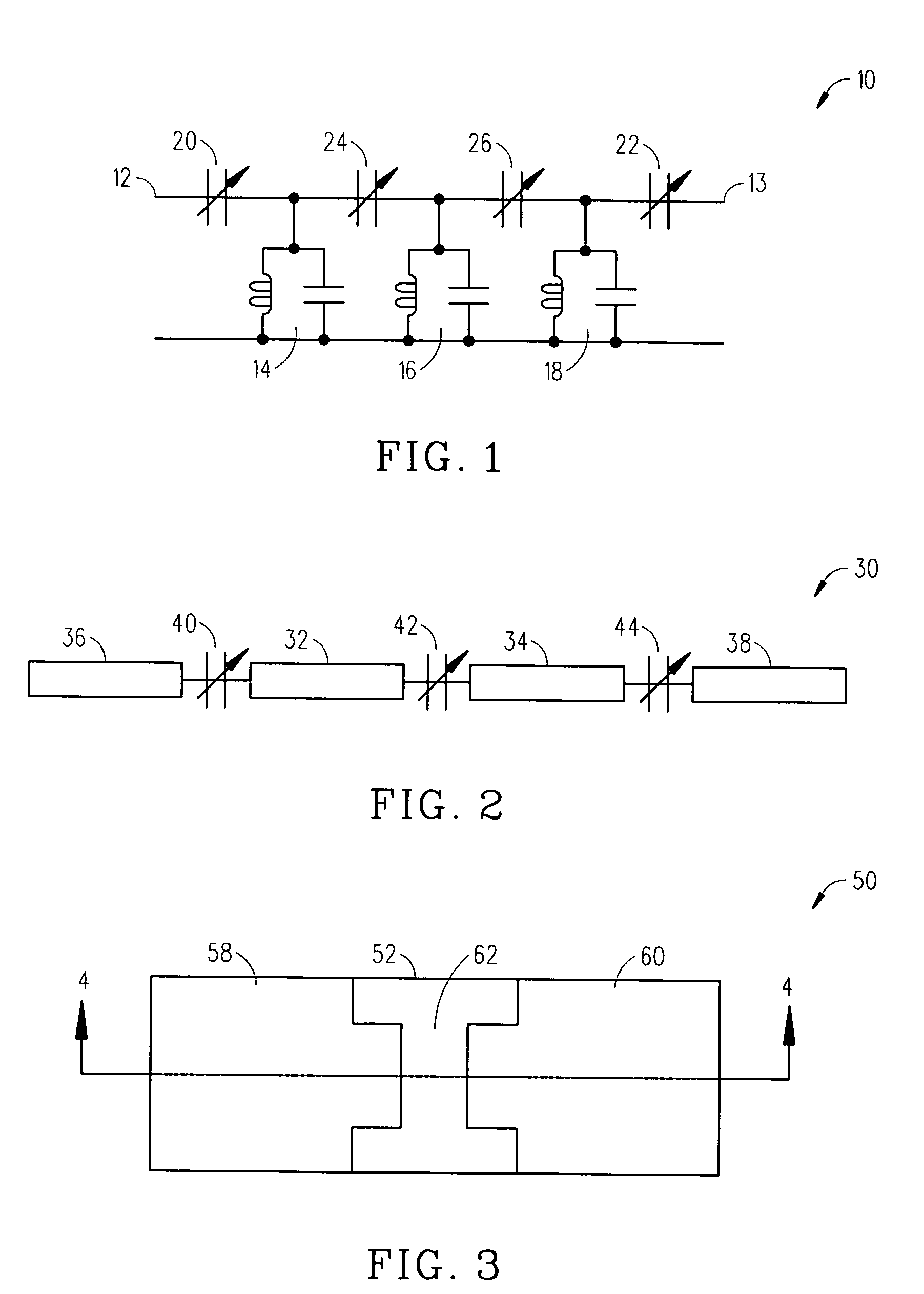
[0028] Referring to the drawings, FIG. 1 is a schematic representation of a lumped element tunable bandwidth band-pass filter 10 constructed in accordance with this invention. Filter 10 includes an input 12, an output 13 and a plurality of resonators 14, 16, 18. A first voltage tunable dielectric access varactor 20 couples input 12 with resonator 14. A second voltage tunable access dielectric varactor 22 couples output 13 with resonator 18. Additional intercavity varactors 24, 26 are connected between adjacent resonators 14, 16, 18. Each of voltage tunable access varactors 20, 22 and each of voltage tunable intercavity or varactors 24, 26 includes a voltage tunable dielectric material having a dielectric constant that varies with an applied control voltage, also called a bias voltage. By changing the control voltage for a respective varactor 20, 22, 24, 26, the capacitance of the respective varactor 20, 22, 24, 26 changes.

[0029] In tunable bandwidth bandpass filter 10 (FIG. 1), the...


PUM


Abstract

An embodiment of the present invention provides an apparatus, comprising a feed forward amplifier capable of receiving an input signal and including a plurality of cancellation loops, wherein at least one of the cancellation loops includes a tunable delay line enabling the reduction of intermodulation distortion and receive band noise when outputs from the plurality of cancellation loops are combined with the input signal to the feed forward amplifier. In an embodiment of the present invention the plurality of cancellation loops may be two cancellations loops and a tunable delay line may be included in both of the cancellation loops. Further, the tunable delay line may be a voltage tunable delay line that includes a voltage tunable dielectric capacitor to facilitate the control of the tunable delay and the voltage tunable dielectric capacitor may include a layer of voltage tunable dielectric material positioned on a surface of a low loss, low dielectric substrate.

Description

CROSS REFERENCED TO RELATED APPLICATIONS [0001] This application is a continuation-in-part of co-pending patent application with attorney docket number JSF01-0088 / WJT08-0093 entitled, “METHOD AND APPARATUS CAPABLE OF INTERFERENCE CANCELLATION” filed, Jun. 14, 2006 and claims the benefit of U.S. Provisional Patent Application Ser. No. 60 / 586,437 filed Jul. 08, 2004. BACKGROUND OF THE INVENTION [0002] Electrically tunable filters have many uses in microwave and radio frequency systems. Compared to mechanically and magnetically tunable filters, electronically tunable filters have the important advantage of fast tuning capability over wide band application. Because of this advantage, they can be used in the applications such as, by way of example and not by way of limitation, LMDS (local multipoint distribution service), PCS (personal communication system), frequency hopping, satellite communication, and radar systems. [0003] Filters for use in radio link communications systems have bee...

Claims


Application Information

Patent Timeline
Patent Type & Authority Applications(United States)
IPC IPC(8): H04B1/04H04K1/02H04L25/03
CPCH03F1/3223H04B1/126H03F1/3229
Inventor SHAMSAIFAR, KHOSRO
Owner PARATEK MICROWAVE INC
Why Eureka
Try Eureka