
Magnetic head and magnetic disk storage apparatus mounting the head

Inactive Publication Date: 2006-01-05
HITACHI GLOBAL STORAGE TECH NETHERLANDS BV
View PDF6 Cites 25 Cited by
  • Summary
  • Abstract
  • Description
  • Claims
  • Application Information

AI Technical Summary

Benefits of technology

[0009] It is therefore a feature of the present invention to provide a magnetic head which prevents data from being erased even when a stray field is applied to HDD in parallel to the surface of a medium and a high-density magnetic disk storage apparatus mounting the head.
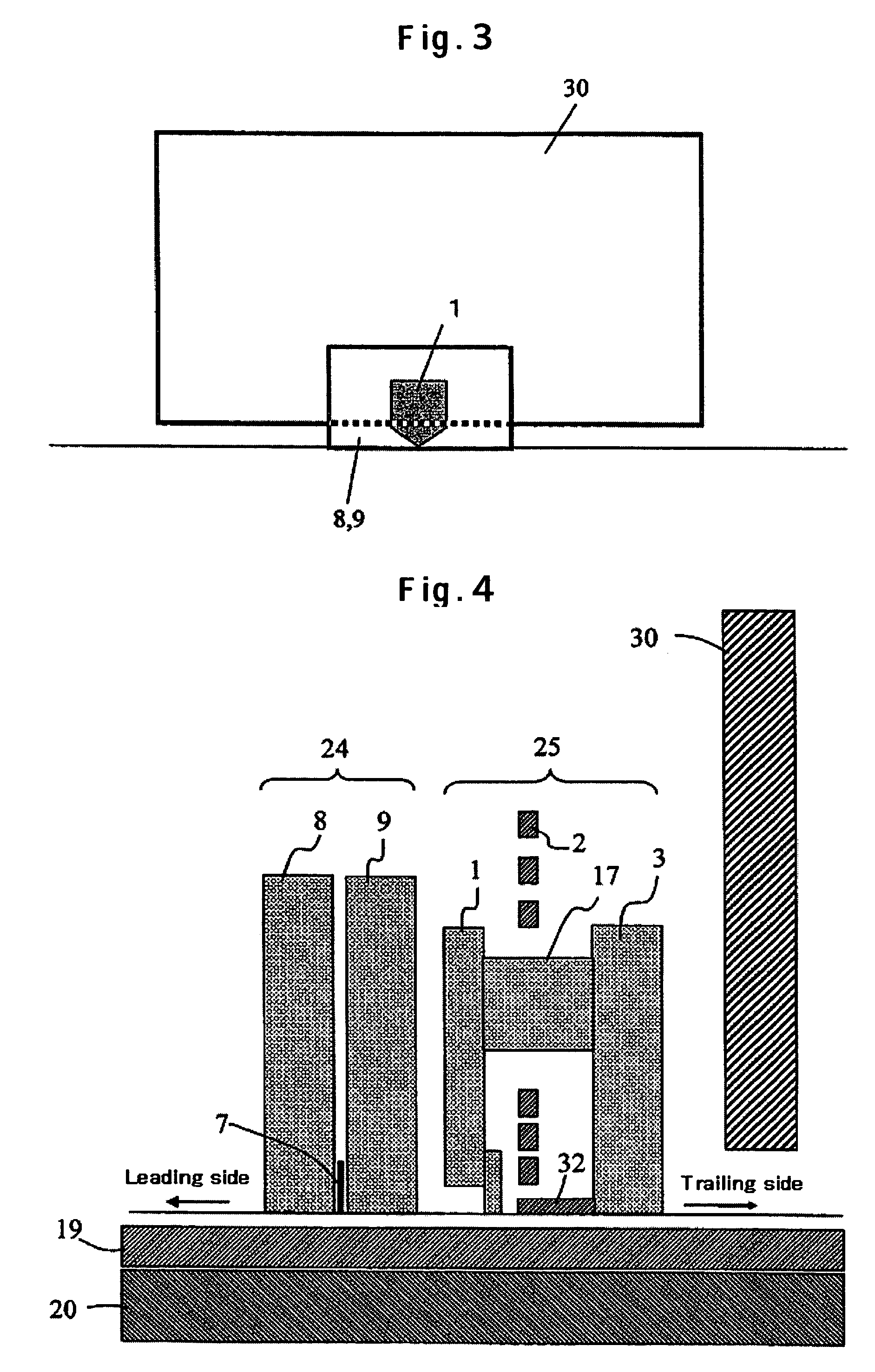
[0010] The magnetic head according to one embodiment of the present invention comprises a read head having a lower shield, an upper shield and a magneto resistive element sandwiched between the lower shield and the upper shield, and a write head having a main pole and an auxiliary pole and a stray-field shield composed of a magnetic layer sandwiched between the auxiliary pole and the main pole. The stray-field shield absorbs a magnetic field floating in HDD and the magnetic flux of an under layer and reduces a magnetic field leaked from the auxiliary pole, lower shield and upper shield so as to reduce a magnetic field to be applied to the magnetic recording layer.
[0011] According to embodiments of the present invention, there can be provided a write head and a magnetic disk device mounting the write head which can reduce a magnetic field leaked from the auxiliary pole, lower shield and upper shield when a stray field is applied to HDD, especially a stray field is applied in parallel to the medium of HDD, thereby preventing the deterioration and erasure of a recording bit of the magnetic recording layer.

Problems solved by technology

Since the magnetic head shown in FIG. 5 has the auxiliary pole and the thin-film coils between the read element and the main pole, the separation between the write head and the read head becomes large and the format efficiency deteriorates.

Method used


Image

  • Magnetic head and magnetic disk storage apparatus mounting the head
  • Magnetic head and magnetic disk storage apparatus mounting the head
  • Magnetic head and magnetic disk storage apparatus mounting the head

Examples


Embodiment Construction

[0027] Specific embodiments of the present invention will be described with reference to the drawings. In the following drawings, the same function parts have the same reference symbols for easy understanding.

[0028]FIG. 9 is a conceptual diagram of a magnetic disk storage apparatus according to an embodiment of the present invention. The magnetic disk storage apparatus writes and reads a magnetization signal with a magnetic head mounted on a slider 13 fixed at the end of a suspension arm 12 at a predetermined position on a magnetic disk (magnetic recording medium) which is turned by a motor 28. By driving a rotary actuator 15, the position (track) in the radial direction of a magnetic disk of the magnetic head can be selected. A write signal to the magnetic head and a read signal from the magnetic head are processed by signal processing circuits 35a and 35b, respectively.

[0029]FIG. 1 is a sectional view of an example of the magnetic head of the present invention. FIG. 2 is a struc...


PUM


Abstract

Embodiments of the invention provide a magnetic head which prevents data on a recording medium from being erased even when a stray field is applied. In one embodiment, an auxiliary pole is sandwiched between a stray-field shield composed of a magnetic layer recessed from the air bearing surface and a main pole. The stray-field shield may be formed on the leading side of the auxiliary pole. A face of the stray-field shield on a medium side may be recessed from an air-bearing-surface of the magnetic head.

Description

CROSS-REFERENCES TO RELATED APPLICATIONS [0001] This application claims priority from Japanese Patent Application No. JP2004-195991, filed Jul. 1, 2004, the entire disclosure of which is incorporated hereinby reference. BACKGROUND OF THE INVENTION [0002] The present invention relates to a perpendicular recording magnetic head and a magnetic disk storage apparatus mounting the perpendicular recording magnetic head. [0003] A magnetic disk storage apparatus comprises a magnetic recording medium and a magnetic head to read and write data on the magnetic recording medium with the magnetic head. To expand the recording capacity per unit area of the magnetic recording medium, the areal recording density must be increased. However, in the current longitudinal recording system, when the bit length to be recorded becomes small, the surface recording density cannot be increased due to thermal fluctuations in the magnetization of the medium. As a solution to this problem, there is a perpendicul...

Claims


Application Information

Patent Timeline
IPC IPC(8): G11B5/127
CPCG11B5/127
Inventor FUKUI, HIROSHIMOCHIZUKI, MASAFUMISUZUKI, KAORI
Owner HITACHI GLOBAL STORAGE TECH NETHERLANDS BV
Learn More