
Apparatus and methods for eliminating DC offset in a wireless communication device

a wireless communication device and wireless communication technology, applied in the direction of dc level restoring means or bias distortion correction, digital transmission, baseband system details, etc., can solve the problem of parasitic direct-current (dc) quantity, especially severe problem, unpredictable phase differen

Active Publication Date: 2005-12-15
THETA IP
View PDF24 Cites 21 Cited by
  • Summary
  • Abstract
  • Description
  • Claims
  • Application Information

AI Technical Summary

Problems solved by technology

A significant problem encountered in the design of direct-conversion receivers is the generation of a parasitic direct-current (DC) quantity, called DC offset, at the output of mixer 120.
The problem is especially severe for standards in which the baseband extends all the way to nearly zero frequencies.
Such phase difference is unpredictable, as it can vary depending on fabrication tolerances and other factors.
Another cause of an unpredictable DC offset is the leakage of a received signal to the local oscillator port.
This includes the output of baseband amplifier 140, resulting in nonlinear operation and thus signal distortion.
In addition, this DC component shifts the desired signal at the output, and can lead to saturation or otherwise inadequate operation of a following stage analog-to-digital converter of the wireless receiver.

Method used


Image

  • Apparatus and methods for eliminating DC offset in a wireless communication device
  • Apparatus and methods for eliminating DC offset in a wireless communication device
  • Apparatus and methods for eliminating DC offset in a wireless communication device

Examples


Embodiment Construction

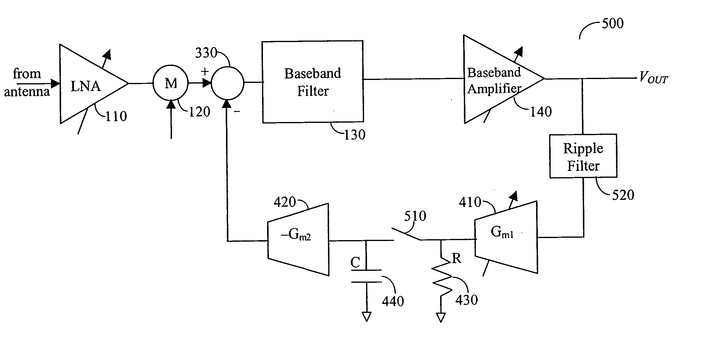
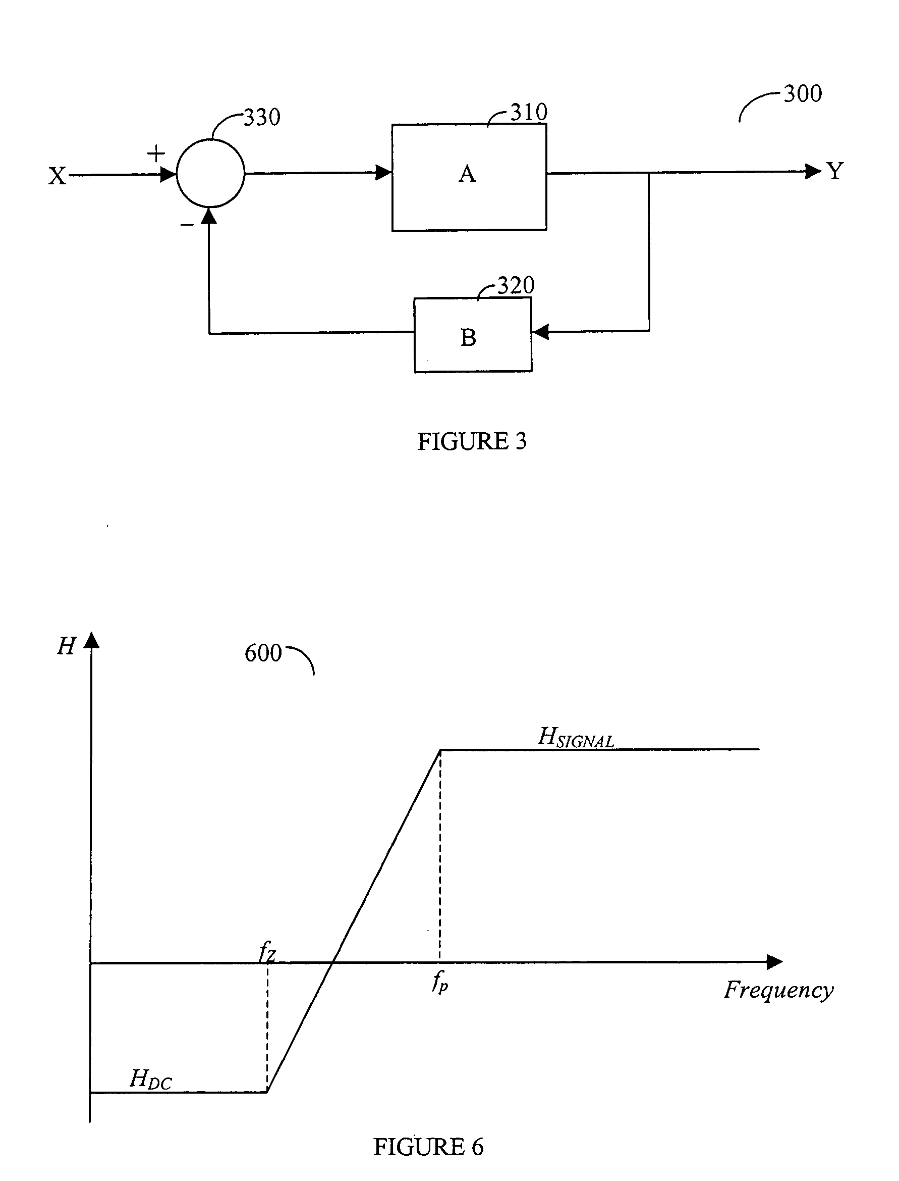
[0015] The present invention comprises a direct current (DC) servo loop that samples at least a portion of the output signal of system 100 shown in FIG. 1, and after amplification, returns it in a negative phase to the input of baseband filter 130. However, it is essential to use different gains for the case of the near DC frequency, i.e., around zero Hertz, while providing a significant gain around the signal frequency band. By adjusting the gain of the feedback loop for the two different frequency ranges, the DC offset is reduced while the signal frequency remains at a desired level.

[0016] In the description to follow, the invention will be described generally, and for purposes of illustration and not limitation, more specifically with respect to orthogonal frequency division multiplexing (OFDM), and at times most specifically in accordance with the IEEE 802.11a standard. However, this should not be viewed as limiting the use of the disclosed invention in such cases as Hiperlan2,...


PUM


Abstract

Apparatus and methods for eliminating DC offset in a wireless communication device operable on a continuous basis or on a sampled basis. In a receive channel, the output of a forward variable gain amplifier is fed back to an RC circuit to charge the capacitor (C) to a voltage dependent on the DC offset in the variable gain amplifier output. The voltage on the capacitor is amplified and summed with the input to the variable gain amplifier. The RC circuit is configured to provide a high gain feedback at DC and very low frequencies, but very low gain at signal frequencies. Preferably the output of the forward variable gain amplifier is fed back to the RC circuit with a gain that is inversely proportional to the forward gain. Disconnection of the capacitor and feedback of the capacitor voltage provides sampled operation. Various embellishments and sample applications are disclosed.

Description

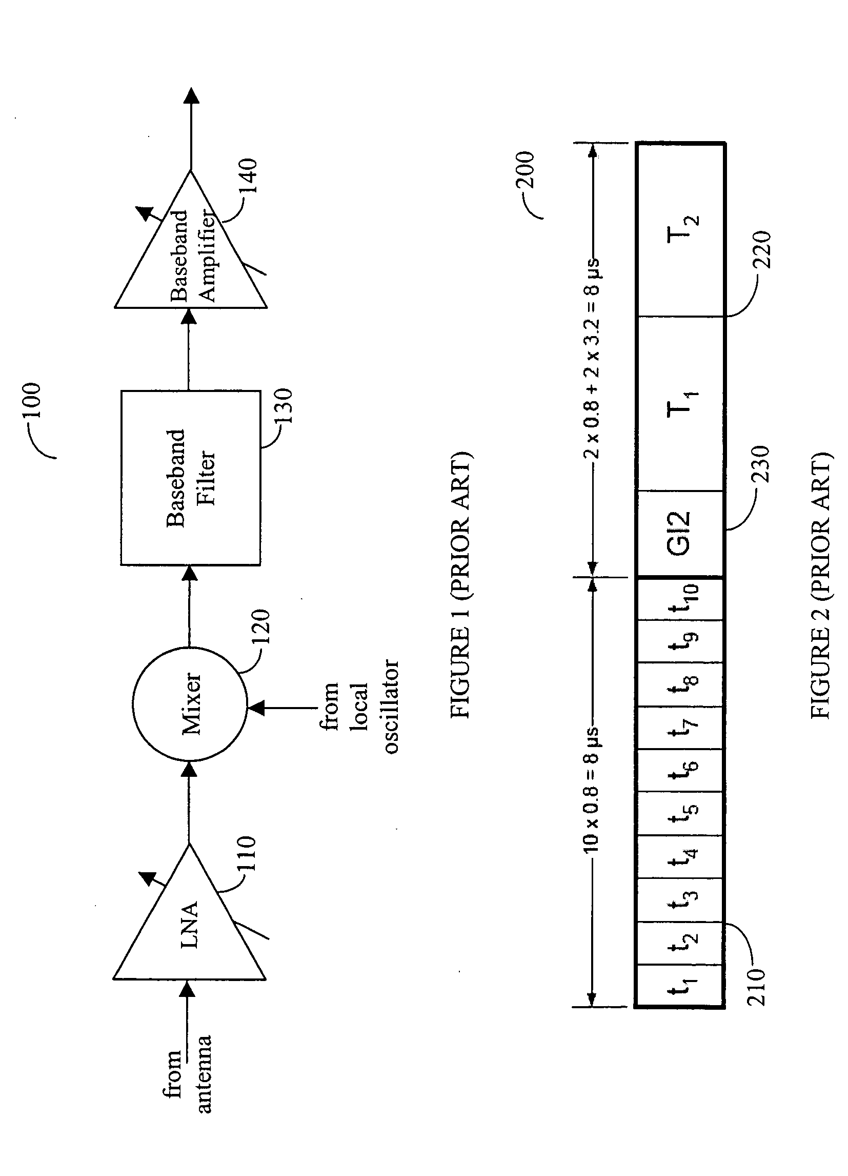
BACKGROUND OF THE INVENTION [0001] 1. Field of the Invention [0002] The present invention relates to direct current (DC) offset cancellation, and more particularly to DC offset cancellation in a wireless communication device. [0003] 2. Prior Art [0004] Receivers are necessary components of communication links, and are used, for example, in two-way cellular phone communications or wireless local area networks. A simplified block diagram of a typical prior-art wireless receiver 100 is shown in FIG. 1. A signal from an antenna is fed to low-noise amplifier (LNA) 110. LNA 110 is a variable gain amplifier controlled by an automatic gain control (AGC) circuit for amplifying weak signals as necessary without introducing much noise. LNA 110 feeds mixer 120, which mixes down the received high-frequency signal to baseband frequencies (including 0 Hz), by effectively multiplying the received and amplified signal with a local-oscillator (LO) signal produced by an oscillator (not shown) in the r...

Claims


Application Information

Patent Timeline
IPC IPC(8): H04B1/06H04B1/30H04L25/06
CPCH04L25/061H04B1/30
Inventor PIPILOS, SPYROS
Owner THETA IP
Learn More