Central screen

a central screen and filter screen technology, applied in the field of filter screen, can solve the problems of increased dynamic pressure loss, increased production loss, and dynamic pressure loss of radial flow, and achieve the effect of reducing the compaction of the chip column, increasing the amount of circulation or extraction flow, and increasing the load of the individual screen

Inactive Publication Date: 2005-12-15
VALMET TECH INC
View PDF8 Cites 0 Cited by
  • Summary
  • Abstract
  • Description
  • Claims
  • Application Information

AI Technical Summary

Benefits of technology

[0019] According to the present invention, the excessive packing of chips in a moving column against an individual screen, and the zone of zero velocity in the middle of the digester, are avoided by using a screen assembly located on the central tube or pipe for liquor withdrawal together with a wall screen. The required outflow is thus divided between the wall screen and the central screen. In a preferred embodiment, the central screen is essentially at the same level as the wall screen.
[0020] The central withdrawal screen structure in the middle of the pressure vessel may be located at a level different from that of the complementary wall screen assembly. In this case, it is so located that liquid flowing towards this central screen has to travel upwards through the chip column, and against the direction of the plug flow. This counter-flow reduces the chip column compaction against the central screen, especially at the bottom part of the screen, and the screen remains open and operational.
[0021] With the screen solutions according to the present invention, the amount of circulation or extraction flows can be increased in proportion to the pulp production rate without increasing the load of an individual screen so much that it would disturb the movement of the chip column and have a negative influence on the quality and quantity of product.

Problems solved by technology

A problem associated with the above-mentioned designs is the radial flow of liquor through the chip bed from the central pipe towards the screen structure at the digester wall.
The chip column causes a dynamic pressure loss for radial flow, this loss being dependant on the flow rate.
Because the chip bed is flexibly subject to any force, this dynamic radial force causes thickening, i.e. packing of the chip column against the screen structure at the vessel inner wall, which in turn results in an increased dynamic pressure loss, etc.
If the screen structure at the digester wall is overloaded by the liquid flow through the chip column, the screen structure is blocked very quickly, and there will be disturbances in the process; the movement of the chip column may even stop, resulting in production losses.
This quench circulation flow, however, increased the amount of liquor flowing from the center of the digester towards the extraction screens, as well as its radial flow velocity, which increased the non-desired chip column packing against the extraction screens.
The additional load due to the quench circulation worsened the operation of the screens in the loaded digesters and the movement of the chip column.
Due to the problems described above, circulations or extraction flows in the digester cannot be maintained at sufficiently high rates, which results in non-desired chemical and temperature gradients.
This has a negative impact on the quality of the product and the production economy.
In the worst case, the operation of the whole digester may stall due to screen blockages.
Physics causes problems in this design as well, as does the location of the screen in relation to the supply of wash liquid.
To be able to force the required amount of liquid from the distribution screen at the wall of the digester to the screen in the middle of the digester, both screens have to be very high in proportion to the digester volume, which makes this construction expensive.
That is why this design has not been supplied commercially for decades.

Method used


Image

  • Central screen
  • Central screen
  • Central screen

Examples


Embodiment Construction

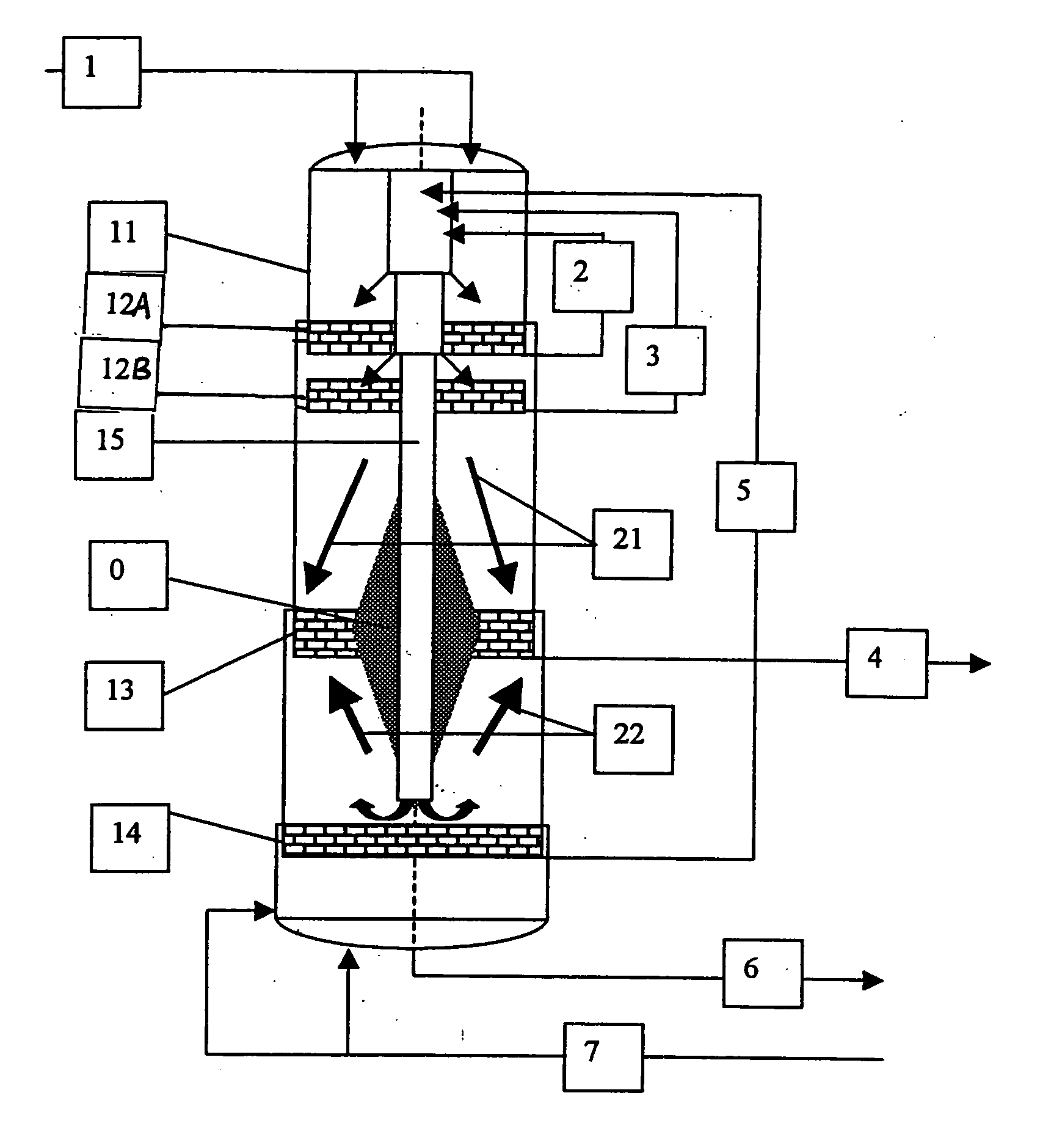
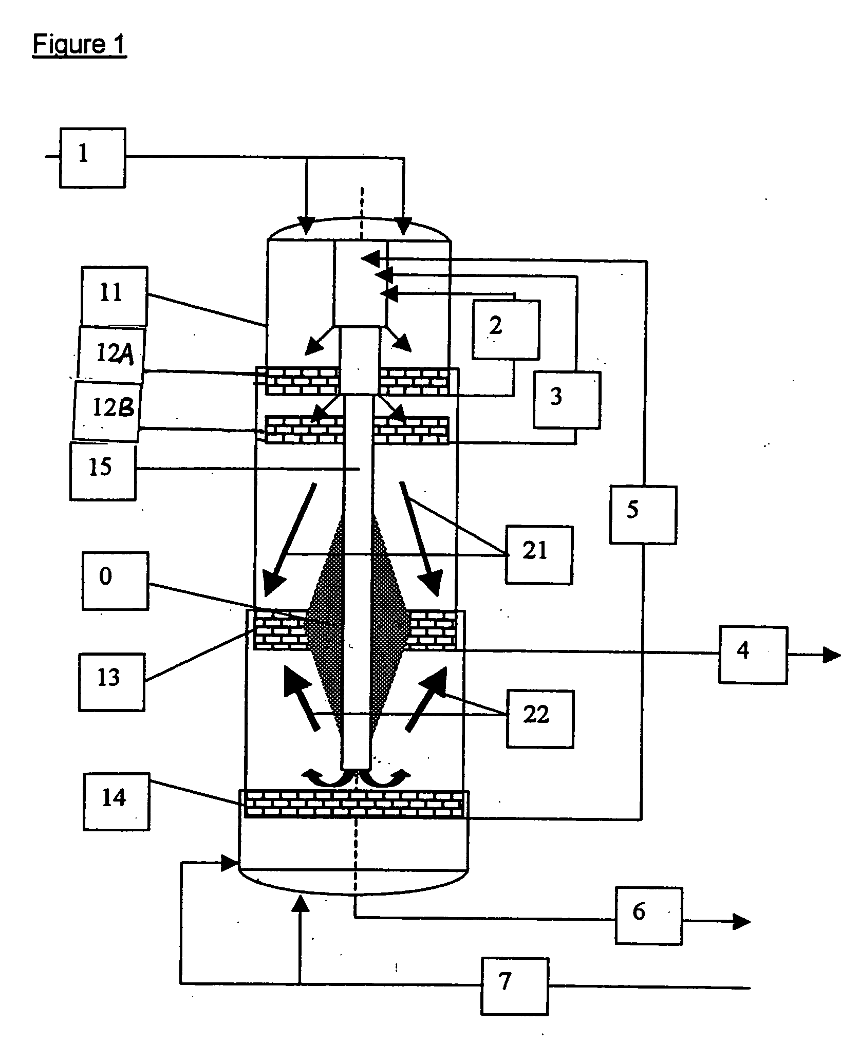
[0028]FIG. 1 shows the general outline of a prior art continuous hydraulic digester. It consists of a pressure vessel (11), upper and lower cooking circulation screens (12), mounted to the upper part of the pressure vessel (11), extraction screens (13) mounted close to the middle part of the vessel, and optional washing circulation screens (14) mounted close to the bottom of the pressure vessel. Along the vertical center line of the vessel (11) there is typically a central pipe (15), which comprises a single pipe or several nested pipes. Through this central pipe, separate circulation entry flows are conveyed to different levels of the vessel (11). General liquid flow directions inside the pressure vessel (11) toward the extraction screens (13) are shown by arrows (21). The chips to be cooked and the liquid cooking chemical are introduced into the upper part of the pressure vessel (11) through a feed line (1). In the pressure vessel (11), the chips form a porous chip column, the por...


PUM

PropertyMeasurementUnit
pressureaaaaaaaaaa
diameteraaaaaaaaaa
chemicalaaaaaaaaaa

Abstract

Methods for continuously producing pulp from lignocellulose-containing material in a digester are disclosed in which the porous lignocellulose-containing material is fed from the top to the bottom of the digester, liquor is pumped through the porous column of lignocellulose-containing material in a predetermined direction, and liquor is simultaneously withdrawn through at least one central screen assembly and through a wall screen assembly. A digester for continuously producing pulp from lignocellulose-containing material is also disclosed.

Description

FIELD OF THE INVENTION [0001] The present invention is related to a method of continuous cooking and washing of cellulose-bearing raw material, especially wood chips, by using an improved liquor circulation pattern. More particularly, the present invention relates to a digester provided with the screens and piping necessary for carrying out this method. BACKGROUND OF THE INVENTION [0002] A continuous digester for pulp manufacture is generally a vertical, essentially cylindrical vessel, receiving a feed of cellulose-bearing raw material (for example, wood chips) in the top of the digester and discharging cooked chips, i.e. pulp, from the bottom of the digester. The vessel is usually a pressure vessel, although this disclosure is not limited to such vessels. At one or several points along the digester, going downwards from the top, there may be an increase in digester diameter. Adjacent such a diameter increase, and generally below it, there is typically an annular screen structure in...

Claims


Application Information

Patent Timeline
Patent Type & Authority Applications(United States)
IPC IPC(8): D21C3/24D21C7/00D21C7/14D21C11/00
CPCD21C3/24D21C7/14
Inventor HERNESNIEMI, LASSENYKANEN, TUOMO
Owner VALMET TECH INC
Why Eureka
Try Eureka