
Method and apparatus for image-based eye tracking for retinal diagnostic or surgery device

Active Publication Date: 2005-12-08
SENSOMOTORIC INSTR FUR INNOVATIVE SENSORIK MBH D B A SENSOMOTORIC INSTR +1
View PDF11 Cites 156 Cited by
  • Summary
  • Abstract
  • Description
  • Claims
  • Application Information

AI Technical Summary

Benefits of technology

[0013] By using an enhanced reference image it is possible to improve the overall accuracy of the eye tracking method, thereby enhancing its performance.
[0034] if an anomaly is detected during said eye tracking, putting said diagnostic or surgical device in a HOLD mode. This enables the system to avoid the negative influence of anomalies in eye motion such as saccades or links.

Problems solved by technology

However, conventional eye tracking techniques suffer from several problems.
One problem is the image quality provided by the system, e.g. the signal-to-noise ratio SNR.
If the SNR is low, then the image processing techniques used for eye tracking are not as accurate as they could be.
Moreover, there are problems which are due to the specific instrumentational configuration.
In case of an OCT system, the measurement beam of the OCT interferes with the fundus imaging due to fact that the illumination spectrum of the beam is close to the imaging spectrum (near IR).
Additionally image is corrupted by acquisition noise and by illumination distortions caused by the pupil size and alignment changes during the procedure. can be applied to any device in which either a measurement scanning beam or surgical laser beam effects the retinal image used for tracking or alignment.

Method used


Image

  • Method and apparatus for image-based eye tracking for retinal diagnostic or surgery device
  • Method and apparatus for image-based eye tracking for retinal diagnostic or surgery device
  • Method and apparatus for image-based eye tracking for retinal diagnostic or surgery device

Examples


Embodiment Construction

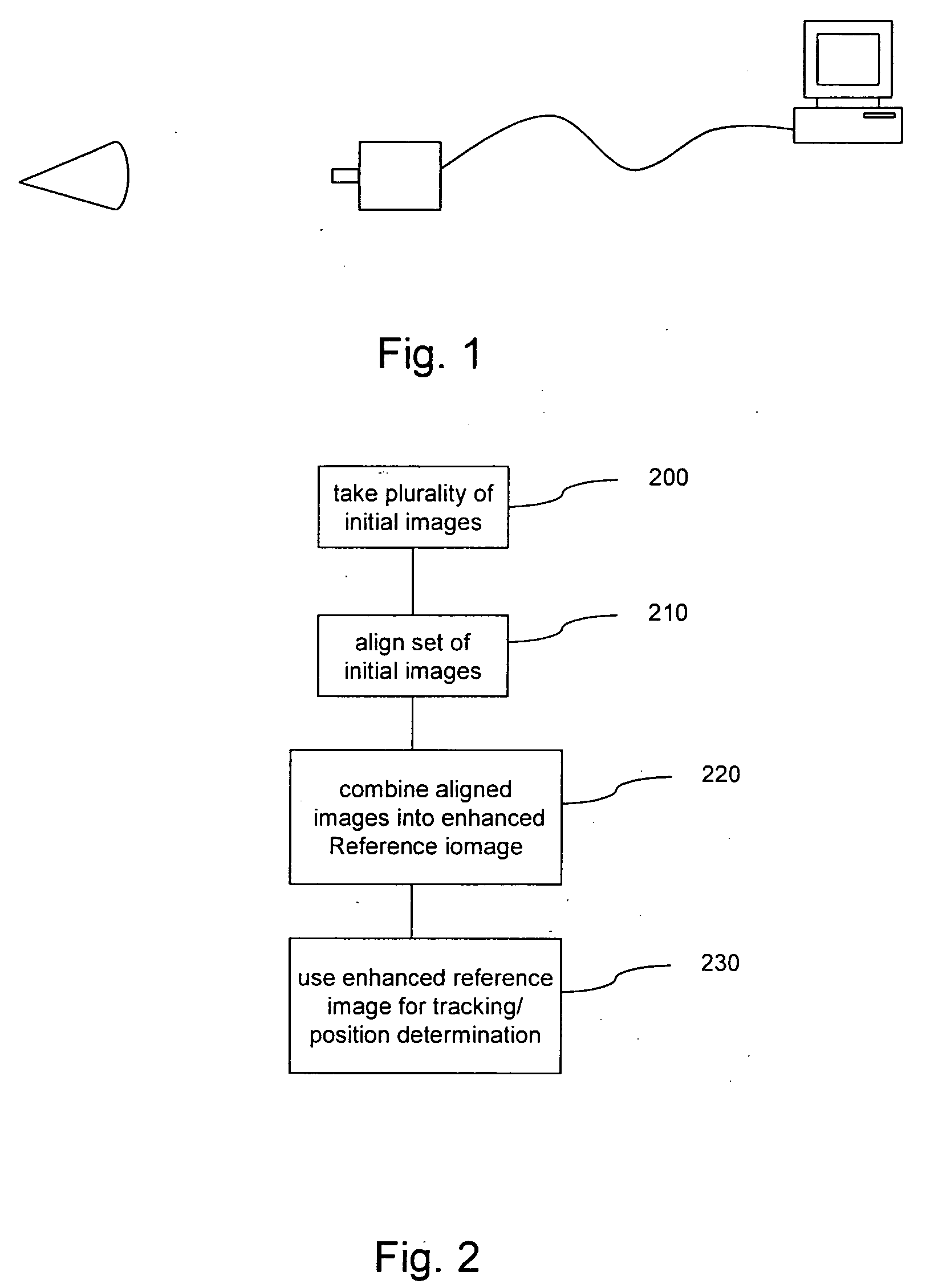
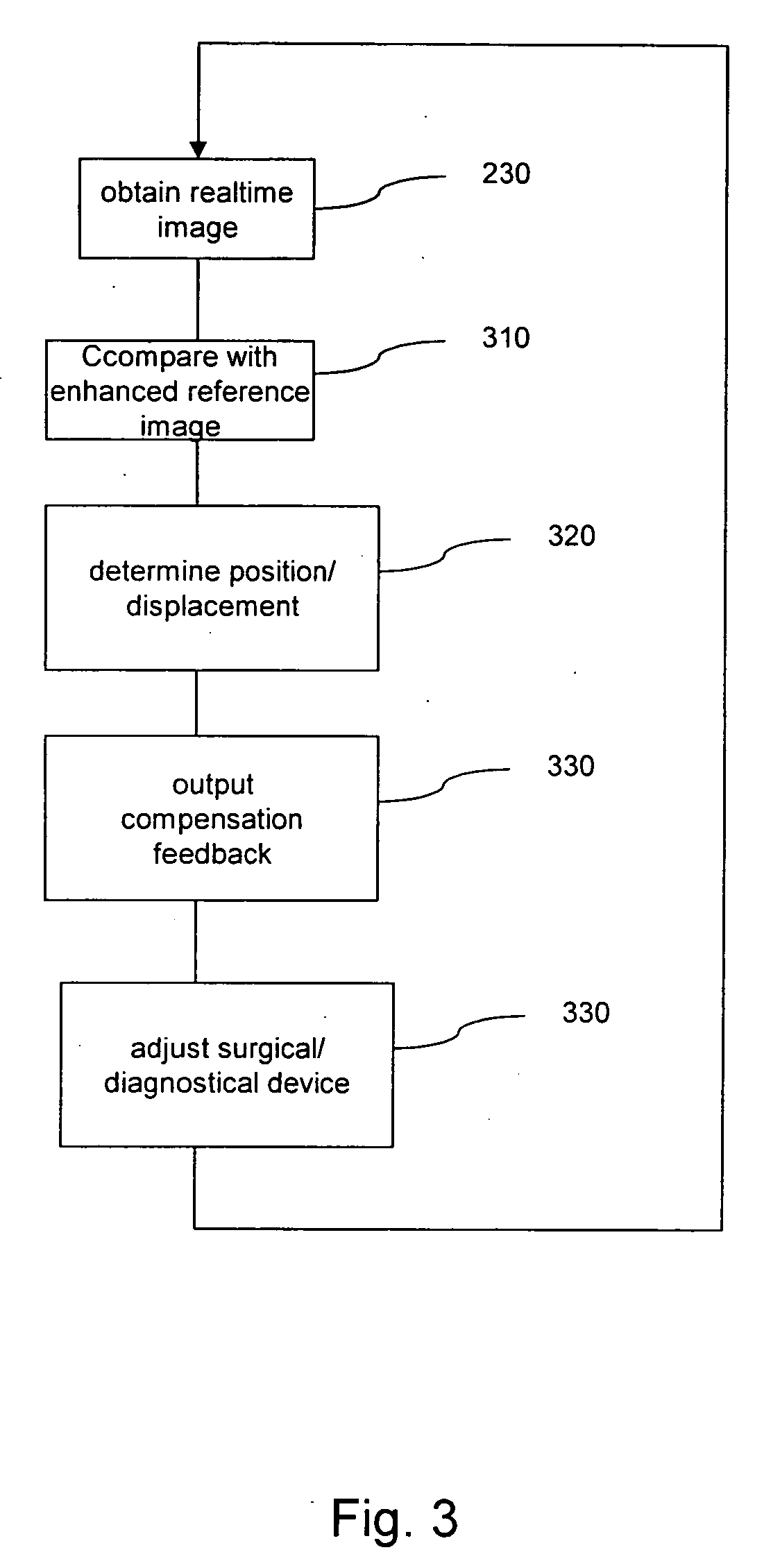
[0050] A first embodiment of the present invention will now be described in connection with FIG. 1. A camera (e.g. a CCD camera) 110 takes video images of an eye 100, and the images are fed to a computer 120. Such an arrangement is equal to a classical eye tracking system and it may also be applied to the present invention. In the conventional eye tracking system, based on the images captured the computer 120“tracks” the eye movement, e.g. by comparing the position of some “landmarks” in the momentary image with the position in the previous image to thereby “track” the movement of the eye. Based on the tracked actual position a feedback signal may be determined which then is used to carry out a position compensation at a surgical or diagnostic device (not shown in FIG. 1).

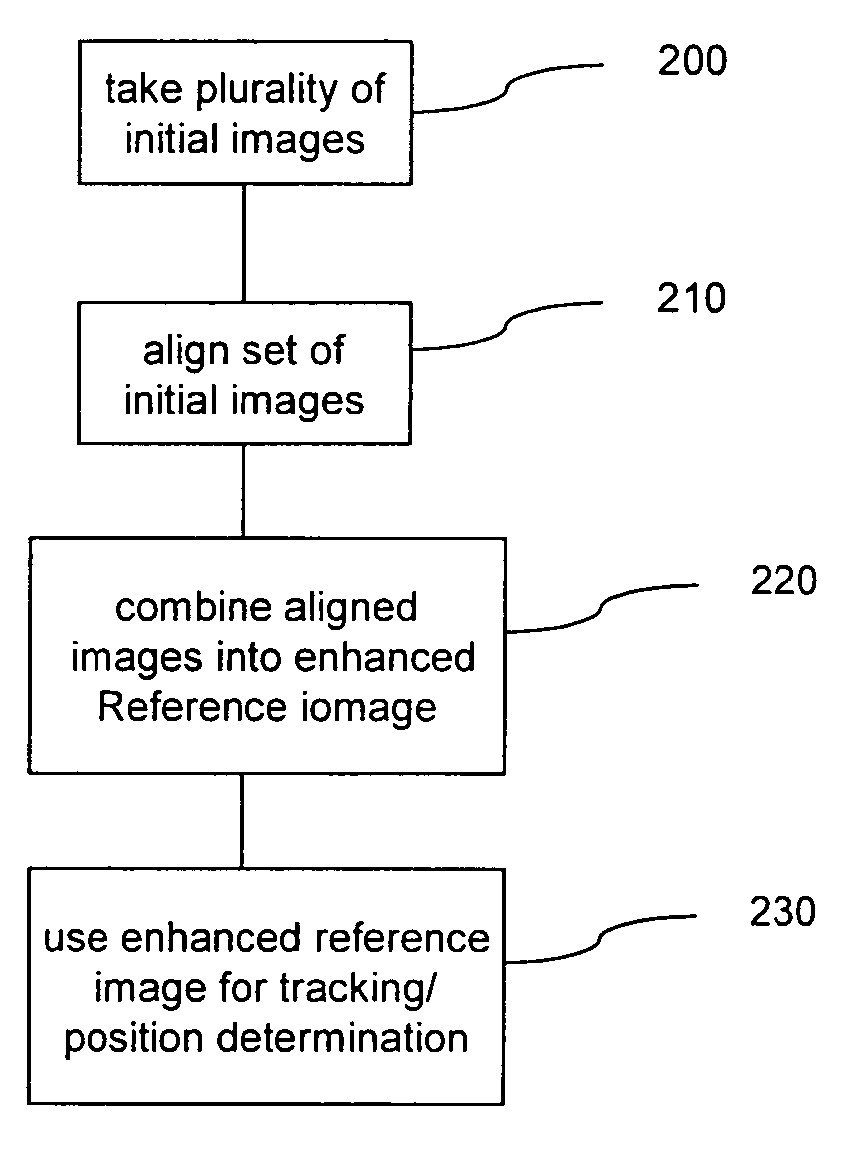
[0051] In order to track the movement of the eye or to determine the position of the eye an instantaneous image of the eye is compared with some reference image. According the present embodiment this reference ima...


PUM


Abstract

An eye tracking method for determining a position of an eye or a part of an eye in an image of an image sequence by performing a comparison between said image and a reference image, said process including: aligning a set of images; computing an enhanced reference image based on a combination of said set of aligned images; and determining said position in said image of said image sequence by comparing said image of said image sequence and said enhanced reference image to yield a motion estimation between said reference image and said image of said sequence.

Description

FIELD OF THE INVENTION [0001] The present invention relates to a method and an apparatus used in image-based tracking of eye movement or position in a retinal diagnostic / surgical device. BACKGROUND OF THE INVENTION [0002] Image-based tracking of eye movement or position is known to be used for several applications such as surgery and diagnostics, one example being a retinal diagnostic / surgical device. However, conventional eye tracking techniques suffer from several problems. One problem is the image quality provided by the system, e.g. the signal-to-noise ratio SNR. If the SNR is low, then the image processing techniques used for eye tracking are not as accurate as they could be. Moreover, there are problems which are due to the specific instrumentational configuration. [0003] One such example is retinal video tracking for a Optical Coherence Tomography (OCT) device for measuring thickness and structure of the retinal layers, but other specific fields such as devices for surgery, d...

Claims


Application Information

Patent Timeline
IPC IPC(8): A61B3/113A61F9/008A61F9/01G06T7/00
CPCA61B3/113A61F9/008A61F2009/00846A61F2009/00872G06T7/0012G06T2207/30041G06T2207/10016G06T7/0016G06K9/0061A61B3/145A61B3/102G06T2207/10101G06V40/193
Inventor TEIWES, WINFRIEDGRECU, HORIA
Owner SENSOMOTORIC INSTR FUR INNOVATIVE SENSORIK MBH D B A SENSOMOTORIC INSTR
Learn More