
Fluid pressure control device

a control device and fluid pressure technology, applied in the direction of pump control, servomotor, servomotor circuit, etc., can solve the problems of complicated structure of connecting the solenoid valve and the circuit board, and achieve the effect of easy connection

Inactive Publication Date: 2005-12-01
HITACHI LTD
View PDF11 Cites 20 Cited by
  • Summary
  • Abstract
  • Description
  • Claims
  • Application Information

AI Technical Summary

Benefits of technology

The present invention provides a fluid pressure control device that makes it easy to connect the solenoid valve and the circuit board. The device includes a housing having a hydraulic circuit, a pump built into the housing, a motor for driving the pump, a circuit board for controlling the motor, and a solenoid valve for changing the amount of venting of the hydraulic circuit. The motor, the circuit board, and the solenoid valve are disposed on the same side of the housing. The device can be assembled by assembling the first assembly to the second assembly along a same axis. The technical effects of the invention include easy connection of the solenoid valve and the circuit board, improved assembly efficiency, and simplified operation and maintenance.

Problems solved by technology

As a result, the structure for connecting the solenoid valve and the circuit board is complicated.

Method used


Image

  • Fluid pressure control device
  • Fluid pressure control device
  • Fluid pressure control device

Examples


Embodiment Construction

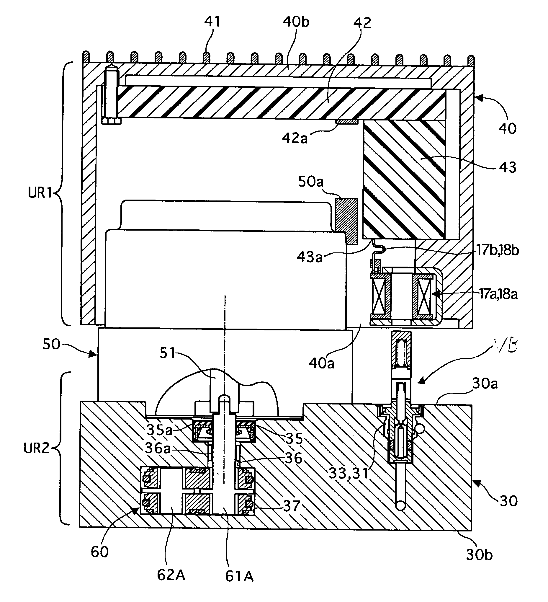
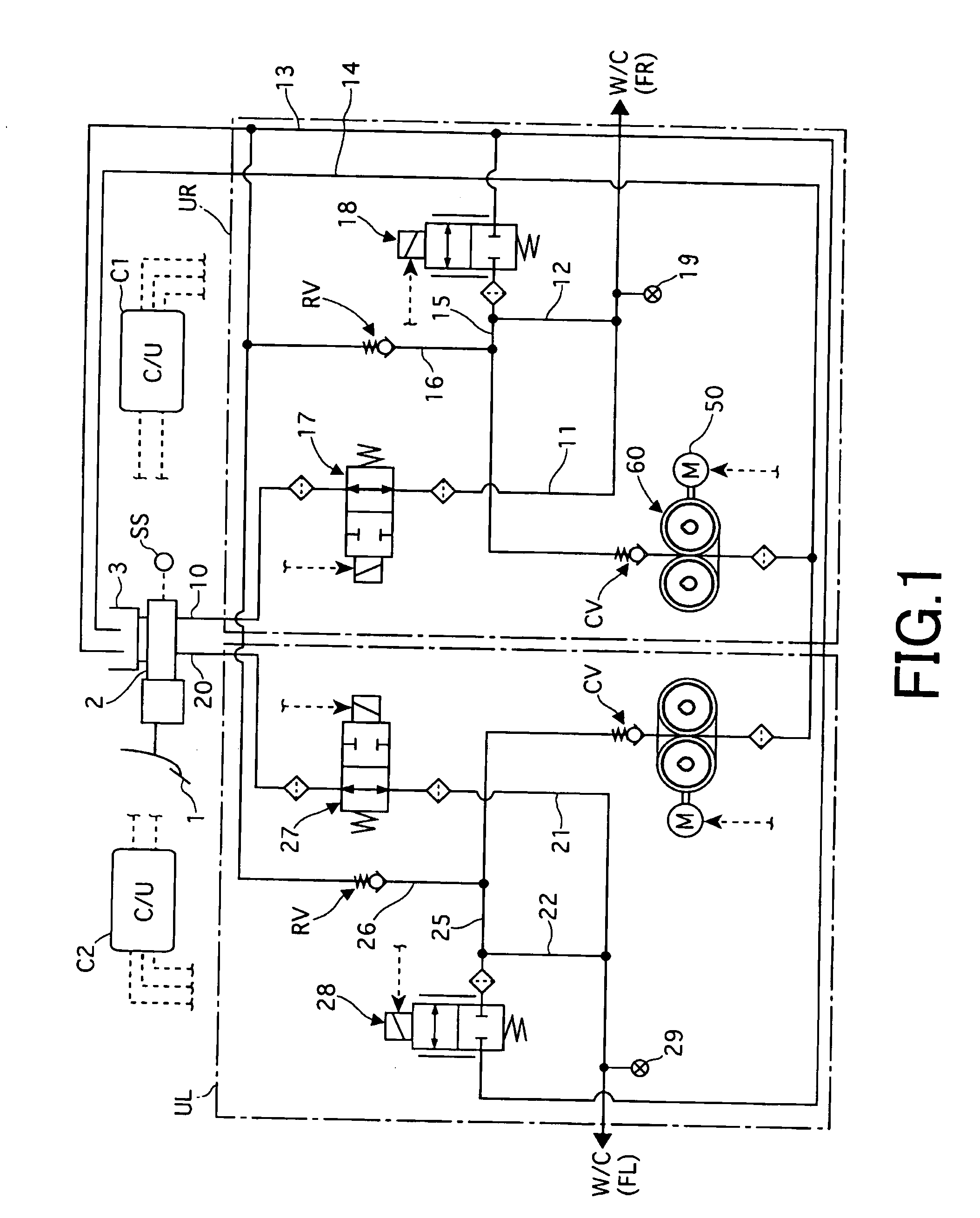
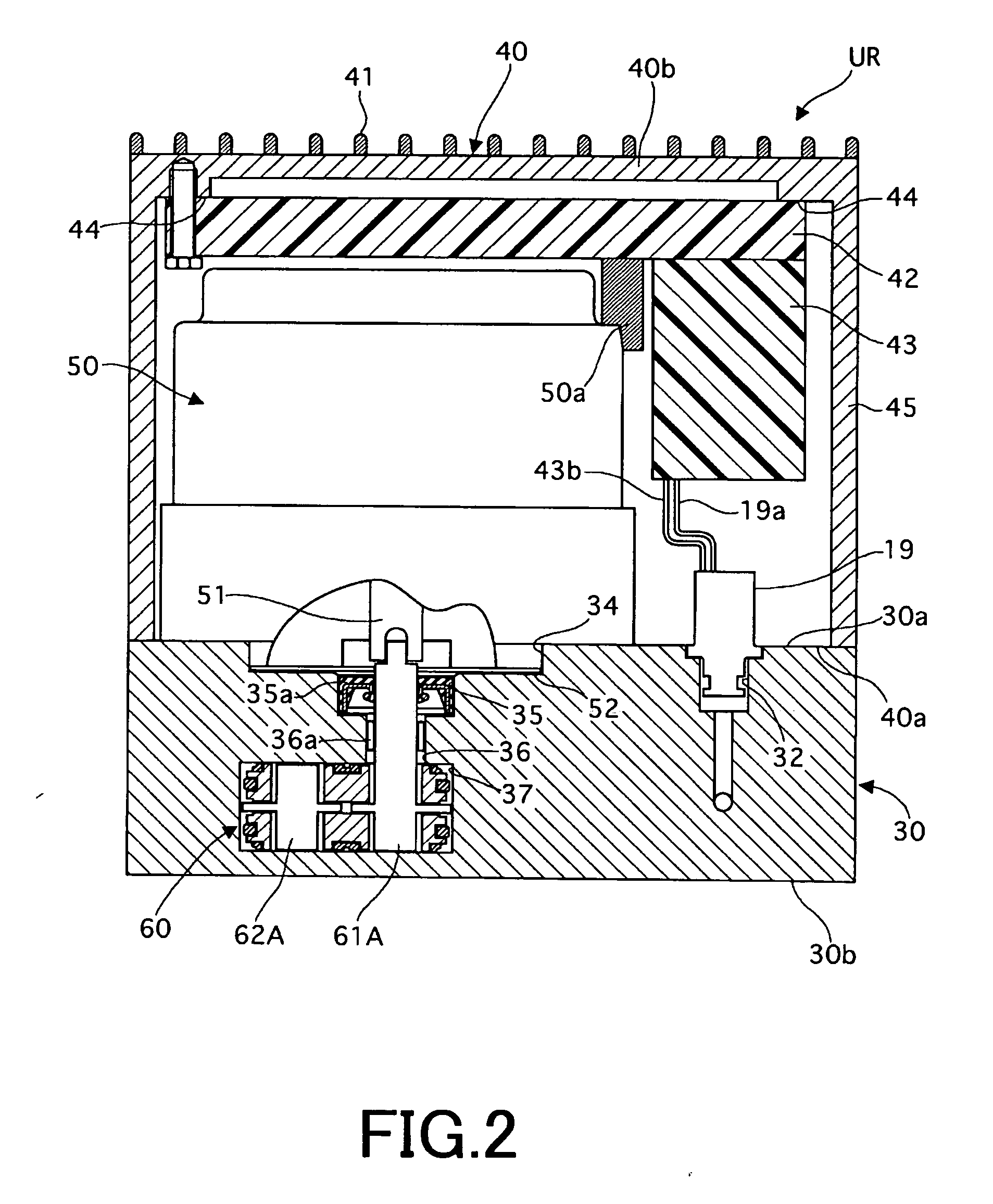
[0025] Referring to the drawings, a description is made of embodiments of the present invention.

[0026] As seen in FIG. 1, a fluid pressure control device is applied as a brake-by-wire system for a motor vehicle. This embodiment is a front wheel only system. Of course, the fluid pressure control device can be applied as a rear wheel system or a different system.

[0027] A brake pedal 1 to be operated by a driver has a master cylinder 2 for generating a braking pressure. For example, the master cylinder can be a so-called tandem type master cylinder. The master cylinder 2 has a stroke simulator for simulating a brake stroke when a shut valve 17, 27 is closed. When the shut valve 17, 27 is open, the braking pressure can be supplied from the master cylinder 2 to each wheel cylinder W / C. Moreover, master cylinder 2 has a stroke sensor SS for sensing a stroke of the brake pedal 1.

[0028] A right path 10 for supplying a pressure of the master cylinder 2a to a right unit UR and a left path ...


PUM


Abstract

A fluid pressure control device including a housing having a hydraulic circuit, a pump built into the housing, a motor for driving the pump, a circuit board for controlling the motor and a solenoid valve for changing an amount of venting of the hydraulic circuit. The motor, the circuit board and the solenoid valve dispose on a same side of the housing.

Description

CROSS-REFERENCE TO RELATED APPLICATIONS [0001] The entire contents of Japanese Patent Application P2004-156303 filed May 26, 2004 and the entire contents of Japanese Patent Application P2005-115642 filed Apr. 17, 2005 are incorporated herein by reference. BACKGROUND OF THE INVENTION [0002] The present invention relates to a fluid pressure control device, and more particularly, to a fluid pressure control device applied as a vehicle break device. [0003] A fluid pressure control device is disclosed in JP-A-10-129445, wherein the device includes a housing, a motor, a solenoid valve and a circuit board for controlling the motor and the solenoid valve. The motor and the circuit board are disposed on a first side surface of the housing, and the solenoid valve is disposed on a different side surface of the first side surface. [0004] However, in the above case, the solenoid valve and the circuit board are disposed on different side surfaces of the housing. Therefore, a distance between the ...

Claims


Application Information

Patent Timeline
Patent Type & Authority Applications(United States)
IPC IPC(8): B60T8/36F15B1/26F15B11/00F15B21/08
CPCB60T8/368F15B1/26F15B11/006F15B21/08F15B2211/20515F15B2211/20576F15B2211/7056F15B2211/327F15B2211/6309F15B2211/6313F15B2211/6336F15B2211/6651F15B2211/6656F15B2211/3144
Inventor NAKAZAWA, CHIHARU
Owner HITACHI LTD
Learn More