
Dual function prosthetic bone implant and method for preparing the same

a bone implant and dual function technology, applied in the field of prosthetic bone implants, can solve the problems of replacing the metallic cage sitting between the vertebrae, and achieve the effect of improving the bioresorbability of the implan

Inactive Publication Date: 2005-12-01
CALCITEC
View PDF99 Cites 27 Cited by
  • Summary
  • Abstract
  • Description
  • Claims
  • Application Information

AI Technical Summary

Benefits of technology

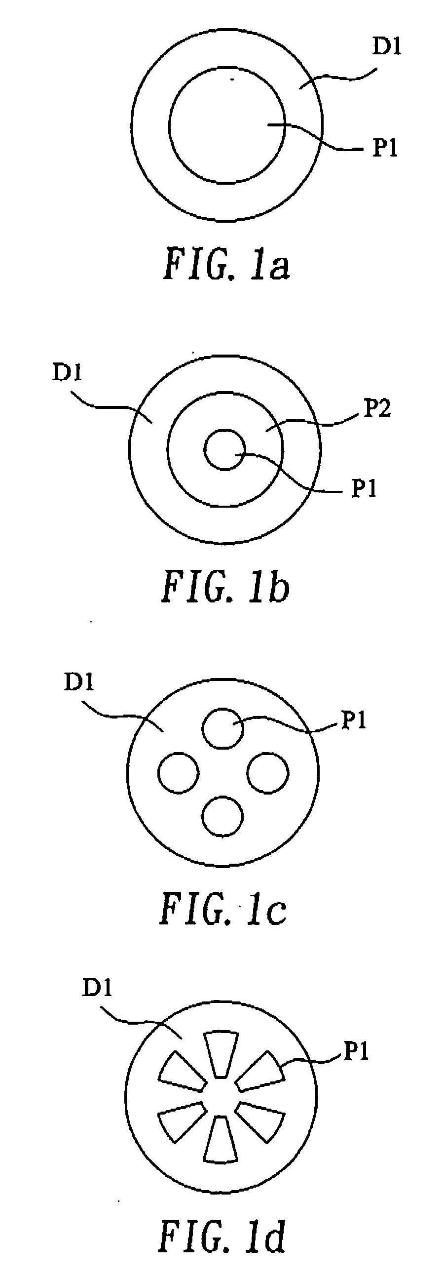
[0008] The prosthetic bone implant constructed according to the present invention is made of a hardened calcium phosphate cement having an apatitic phase as a major phase, which comprises a dense cortical portion bearing the majority of load and a porous cancellous portion allowing a rapid blood / body fluid penetration and tissue ingrowth.
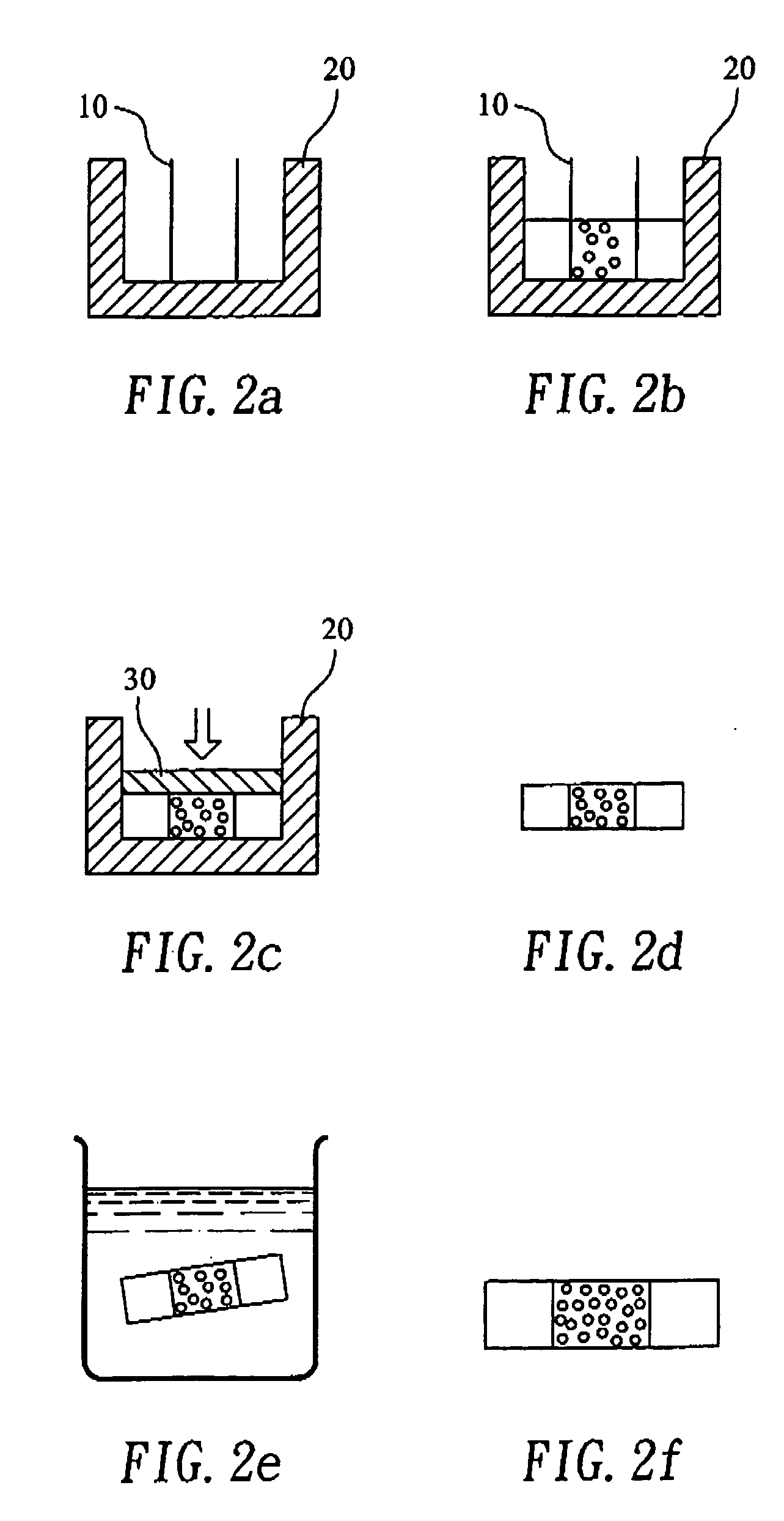
[0009] The prosthetic bone implant of the present invention is made by a novel technique, which involves immersing an article molded from two different pastes of calcium phosphate cement (CPC), one of them having an additional pore-forming powder, in a liquid for a period of time, so that the compressive strength of the molded CPC article is significantly improved after removing from the liquid while the pore-forming powder is dissolved in the liquid, creating pores in a desired zone or zones of the molded article.
[0013] 3. The dense cortical portion of the prosthetic bone implant made according to the present invention contains significant amount of micro- and nano-sized porosity, that improves bioresorbability thereof. Conventional high temperature-sintered HA block, on the other hand, does not possess sufficient micro / nano-sized porosity and is not bioresorbable.
[0014] 4. The porous cancellous portion of the prosthetic bone implant made according to the present invention possesses a porosity greater than 40% in volume, prepferably 40-90%, allowing rapid blood / body fluid penetration and tissue ingrowth, thereby anchoring the prosthetic bone implant.

Problems solved by technology

An inevitable disadvantage of this fusion device is the sinking of the metallic cage sitting between two vertebrae to replace or repair a defect spinal disk, because the hardness and the relatively small size of the cage wear out or break the bone tissue, and in particular the endplate of the vertebra.

Method used


Image

  • Dual function prosthetic bone implant and method for preparing the same
  • Dual function prosthetic bone implant and method for preparing the same
  • Dual function prosthetic bone implant and method for preparing the same

Examples


example 1

Effect of Immersion Time on Compressive Strength of CPC Block

[0073] To a setting solution of 1M phosphoric acid solution (pH=5.89) the ND-CPC powder from PREPARATIVE EXAMPLE 3 was added in a liquid / powder ratio (L / P ratio) of 0.4, i.e. 4 ml liquid / 10 g powder, while stirring. The resulting paste was filled into a cylindrical steel mold having a length of 12 mm and a diameter of 6 mm, and was compressed with a gradually increased pressure until a maximum pressure was reached. The maximum pressure was maintained for one minute, and then the compressed CPC block bs removed from the mold. At the 15th minute following the mixing of the liquid and powder, the compressed CPC block was immersed in a Hanks' solution for 1 day, 4 days, and 16 days. Each test group of the three different periods of immersion time has five specimens, the compressive strength of which was measured by using a AGS-500D mechanical tester (Shimadzu Co., Ltd., Kyoto, Japan) immediately following the removal thereof ...

example 2

Effect of Whiskers on Compressive Strength of TTCP / DCPA-Based CPC Block

[0075] The procedures of EXAMPLE 1 were repeated by using the C-CPC powder prepared in PREPARATIVE EXAMPLE 2 and the ND-CPC powder prepared in PREPARATIVE EXAMPLE 3. The maximum pressure used to compress the CPC paste in the mold in this example was 156.2 MPa. The results for one-day immersion time are listed in Table 2.

TABLE 2CompressiveStandardCPC powderstrength (MPa)deviation (MPa)C-CPC (no whisker) 62.35.0ND-CPC (with whisker)138.08.2

[0076] It can be seen from Table 2 that the compressive strength, 62.3 MPa, of the immersed compressed CPC block prepared from the conventional CPC powder (no whisker) is about 1.7 times of that (37.3 MPa) of the non-immersed compressed CPC block in Table 1, and the compressive strength, 138.0 MPa, of the immersed compressed CPC block prepared from the non-dispersive CPC powder (with whisker) is about 3.7 times of that of the non-immersed compressed CPC block in Table 1

example 3

Effect of Whiskers on Compressive Strength of TTCP-Based CPC Block

[0077] Ca4(PO4)2O (TTCP) powder as synthesized in PREPARATIVE EXAMPLE 1 was sieved with a #325 mesh. The sieved powder has an average particle size of about 10 μm. To the TTCP powder HCl aqueous solution (pH=0.8) was added according to the ratio of 1 g TTCP / 13 ml solution. The TTCP powder was immersed in the HCl aqueous solution for 12 hours, filtered rapidly and washed with deionized water, and filtered rapidly with a vacuum pump again. The resulting powder cake was dried in an oven at 50° C. The dried powder was divided into halves, ground for 20 minutes and 120 minutes separately, and combined to obtain the non-dispersive TTCP-based CPC powder, the particles of which have whisker on the surfaces thereof. A setting solution of diammonium hydrogen phosphate was prepared by dissolving 20 g of diammonium hydrogen phosphate, (NH4)2HPO4, in 40 ml deionized water. The procedures in EXAMPLE 1 were used to obtain the wet s...


PUM

PropertyMeasurementUnit
Temperatureaaaaaaaaaa

Abstract

The present invention discloses a prosthetic bone implant made of a hardened calcium phosphate cement having an apatitic phase as a major phase, which includes a dense cortical portion bearing the majority of load and a porous cancellous portion allowing a rapid blood / body fluid penetration and tissue ingrowth.

Description

PRIORITY CLAIM [0001] This application claims priority to Non-Provisional patent application Ser. No. 10 / 852,167 entitled “DUAL FUNCTION PROSTHETIC BONE IMPLANT AND METHOD FOR PREPARING THE SAME” filed on May 25, 2004.BACKGROUND OF THE INVENTION [0002] 1. Field of the Invention [0003] The present invention is related to a prosthetic bone implant made of a hardened calcium phosphate cement having an apatitic phase as a major phase, and in particular to a prosthetic bone implant comprising a dense cortical portion bearing the majority of load and a porous cancellous portion allowing a rapid blood / body fluid penetration and tissue ingrowth. [0004] 2. Description of the Related Art [0005] It is advantageous if a prosthetic bone implant is bioresorbable and is supportive at the same time. Accordingly, an article made of calcium phosphate will be preferable than that made of a metal, if the former has strength which is comparable to a human cortical bone. One way of making such a bone imp...

Claims


Application Information

Patent Timeline
IPC IPC(8): A61F2/00A61F2/28A61F2/38A61F2/46A61L27/46A61L27/56B27N3/00C04B28/34D04H1/00
CPCA61F2/28A61F2/4644A61F2002/30535A61F2250/0058A61L27/46A61L27/56C04B28/346C04B2111/00836C04B22/082C04B22/10C04B38/04C04B40/0028C04B40/0259C04B40/0286C04B22/16C04B24/04C04B22/06C04B40/0263
Inventor LIN, JIIN-HUEY CHERNJU, CHIEN-PINGTSAI, CHIH-HUNG
Owner CALCITEC
Learn More