
Optimisation mechanism for frequency reuse

a frequency reuse and frequency optimisation technology, applied in the field of mobile telecommunication networks, can solve the problems of reducing network quality, inflexible expansion, and relative slow deployment of installing lines, and achieve the effects of minimizing quality degradation, reducing interference, and optimizing system quality

Inactive Publication Date: 2005-11-03
TELEFON AB LM ERICSSON (PUBL)
View PDF9 Cites 22 Cited by
  • Summary
  • Abstract
  • Description
  • Claims
  • Application Information

AI Technical Summary

Benefits of technology

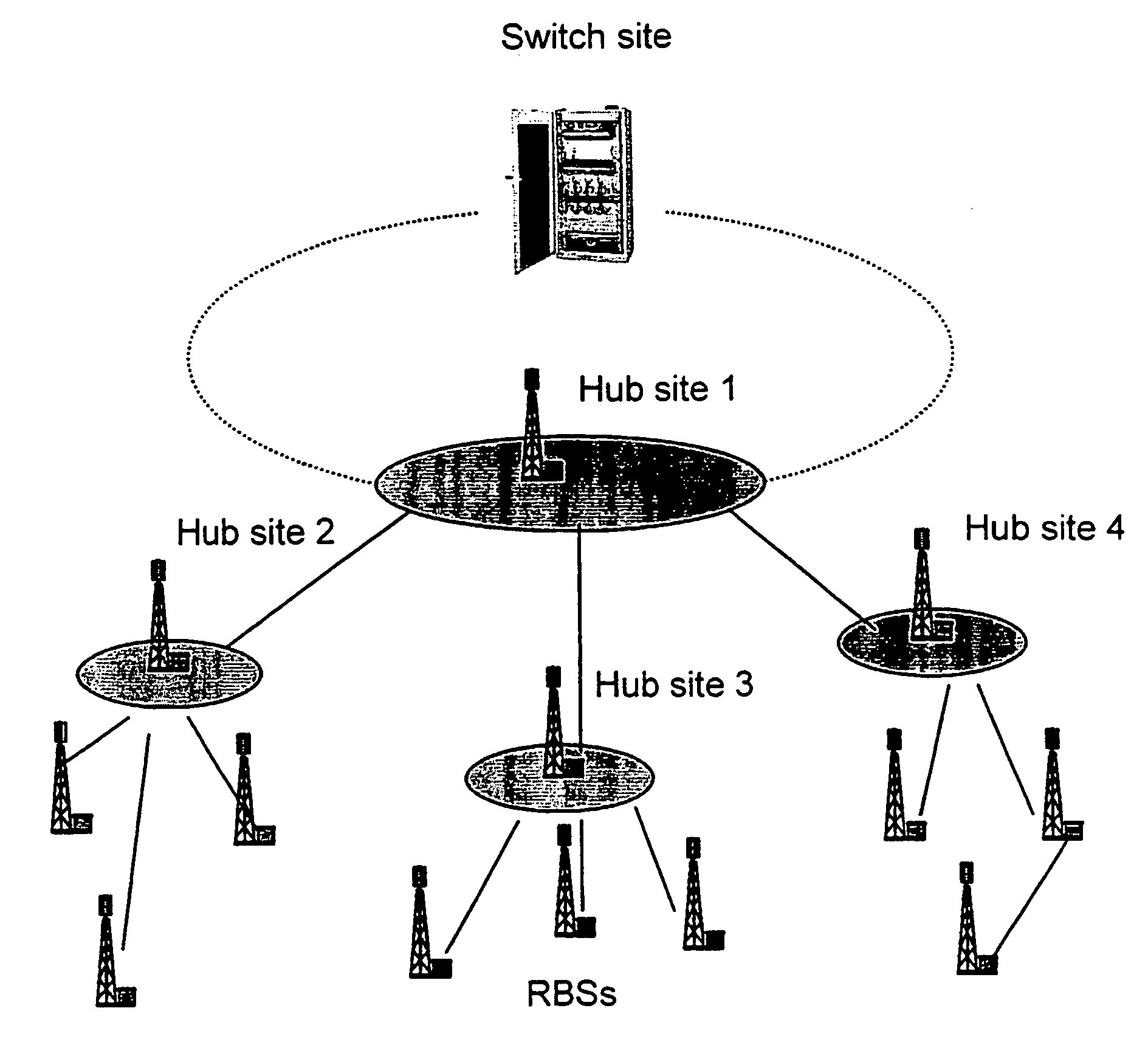
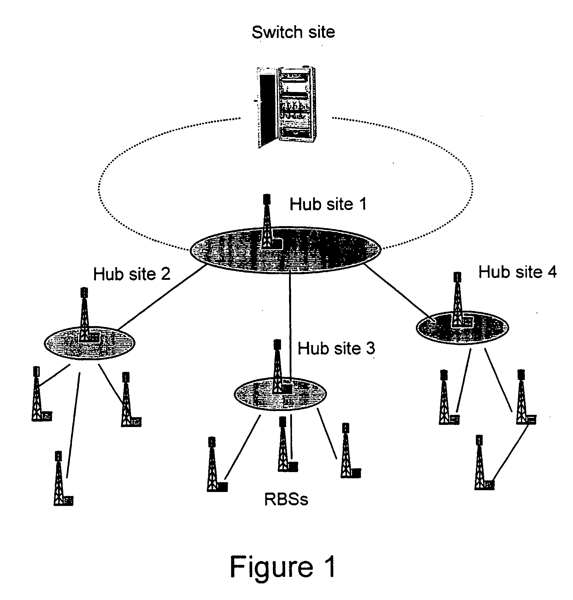
[0006] Briefly described and in accordance with embodiments and related features thereof, there is provided a method and system for a network planning mechanism for the optimisation of system quality associated with frequency reuse for a mobile network infrastructure and business access applications, by using an intelligent combination of microwave point-to-point and point-to-multipoint links in Broadband Wireless Access Systems or LMDS, for example. In an embodiment of the invention, Radio Base Stations (RBSs) sites can be connected to the Switch site by a combination of fibre optic lines, leased lines, or preferably microwave links. The embodiment enables traffic from several end sites to be concentrated at selected hub sites. By way of example, the network planning of the point-to-point and point-to-multipoint links can be chosen to enable a first RBS site to be connected to a second RBS site by means of a point-to-point terminal such that the access terminal, co-located with the second RBS site, routes the traffic from both the first RBS site and the second RBS site to the Hub site. This enables the traffic of the first RBS site to be much less affected by co-channel interference from a remote point-to-multipoint Hub site.
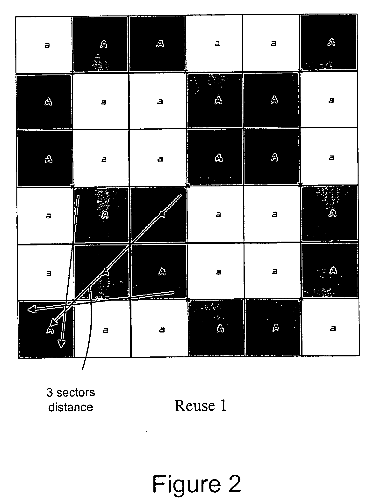
[0007] In a system aspect of the invention, the system is optimised by minimizing the quality degradation that can be experienced due to excessive interference inside a certain portion of the point-to-multipoint covered sector by means of a combined point-to-multipoint and point-to point link solution. The RBS in the planning phase that experiences excessive interference in the direction to the hub, is not directly connected the point-to-multipoint hub, but through a point-to-point link connecting to an access terminal, co-located with a different RBS (or business user), in line of sight with the previous one. The access terminal in turn connects the point-to-multipoint hub allowing a frequency reuse factor of one to be deployed. The point-to-point link uses a portion of the point-to-multipoint frequency block consisting of a single wideband channel, without using a dedicated frequency, thus allowing the safe use of a frequency reuse factor of one that results in significantly reduced interference.

Problems solved by technology

However, using leased T1 or E1 lines generally involves leasing them from a fixed telephone provider that requires paying what can be expensive monthly charges to someone who can be a direct competitor.
Alternatively, operators can use their own wire lines, but this is often unattractive due to the high cost of installation from digging and laying the lines of building the infrastructure.
Another disadvantage is that the relatively slow deployment of installing lines and the inflexibility for expansion becomes an important limitation in industries experiencing fast growth such as mobile communications.
Factors that lower network quality include spectrum efficiency and excessive interference, which can be attributed to inefficient traffic resource allocation and high frequency reuse factor in cells.

Method used


Image

  • Optimisation mechanism for frequency reuse
  • Optimisation mechanism for frequency reuse
  • Optimisation mechanism for frequency reuse

Examples


Embodiment Construction

1. Scope

[0015] In an embodiment of the present invention there is provided a mechanism for the optimisation of the frequency reuse, for mobile network infrastructure and business access applications, by means of combined use of microwave point-to-point links and point-to-multipoint, Broadband Wireless Access Systems or Local Multipoint Distribution Systems (LMDS), for example. Deployment of LMDS is particularly attractive since LMDS networks can be rolled out very quickly, offering customers service in a matter of days and weeks, compared with the relatively long time to deploy fibre networks, for example.

[0016]FIG. 1 shows an example of the access network for a mobile network application. The end Radio Base Stations (RBSs) can be connected to the Switch site by a combination of fibre optics, leased lines or microwave links. This last technology has been the preferred one both for economical and speed of deployment reasons. Furthermore, FIG. 1 shows how traffic from several end s...


PUM


Abstract

The present invention describes a network planning mechanism for the optimisation of system quality associated with frequency reuse for a mobile network infrastructure and business access applications, by using an intelligent combination of microwave point-to-point and point-to-multipoint links in Broadband Wireless Access Systems or LMDS, for example. In an embodiment of the invention, Radio Base Stations (RBSs) sites can be connected to the Switch site by a combination of fibre optics, leased lines, or preferably microwave radio links. The embodiment enables traffic from several end sites to be concentrated at selected hub sites (hub site 1-4). The system is optimised by minimizing the quality degradation that can be experienced due to excessive interference inside a certain portion of the point-to-multipoint covered sector by means of the combined point-to-multipoint and point-to point solutions. The RBS, which on the planning phase will experience excessive interference in the direction to the hub, is not directly connected the point-to-multipoint hub, but through a point-to-point link connecting to an access terminal, co-located with a different RBS or business user, in line of sight with the previous one. The access terminal in turn connects the point-to-multipoint hub allowing a frequency reuse factor of one to be deployed.

Description

FIELD OF THE INVENTION [0001] The present invention pertains generally to mobile telecommunication networks and, more specifically, to the optimisation of the system quality associated with frequency reuse. BACKGROUND OF THE INVENTION [0002] In a basic mobile telecommunication network, a mobile switching center (MSC) is linked to a plurality of base transceiver stations by digital transmission links. In GSM, for example, the digital transmission links connect the radio base stations (RBS) to a base station controller (BSC), which controls and manages the base stations and converges the traffic to the MSC. The transmission of voice and data traffic between the base stations and the core network is a vital task and is often referred to as backhaul. Typically, mobile operators employ either leased lines (T1 / E1), privately owned wire lines (including fibre optic lines), or microwave links for backhaul operations. However, using leased T1 or E1 lines generally involves leasing them from ...

Claims


Application Information

Patent Timeline
IPC IPC(8): H04W16/14H04W16/18H04W74/08H04W84/10H04W88/08
CPCH04W16/14H04W16/18H04W88/085H04W84/10H04W74/08
Inventor NASCIMBENE, ANDREABOLLE, ALDO
Owner TELEFON AB LM ERICSSON (PUBL)
Learn More