
Method, system and program product for controlling a single phase motor

a single-phase motor and control technology, applied in the direction of motor/generator/converter stopper, dynamo-electric converter control, multiple dynamo-motor starters, etc., can solve the problems of pwm carrier being dissipated, significant power loss, and inability to control the pwm carrier

Inactive Publication Date: 2005-11-03
IBM CORP
View PDF20 Cites 9 Cited by
  • Summary
  • Abstract
  • Description
  • Claims
  • Application Information

AI Technical Summary

Benefits of technology

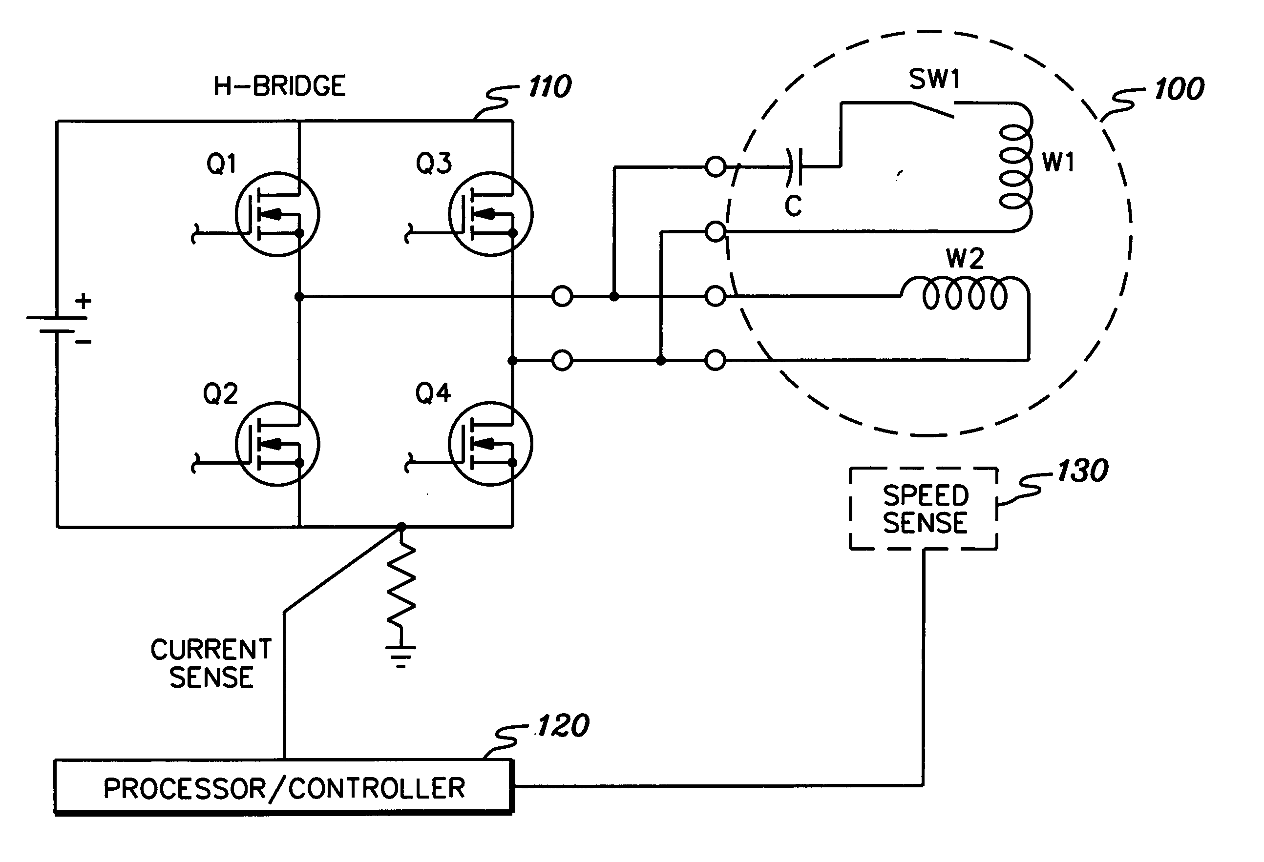
[0006] The shortcomings of the prior art are overcome and additional advantages are provided through a method for controlling a single phase motor. The method includes: driving a single phase motor using a motor drive signal in a first mode, the first mode being either a square wave mode or a pulse width modulation mode; transitioning the motor drive signal from the first mode to a second mode, wherein the second mode is the other of the square wave mode and the pulse width modulation mode, and wherein the transitioning commences after motor speed reaches a first centrifugal switch limit for the motor, the first centrifugal switch limit being a lower centrifugal switch limit when the first mode is the square wave mode, and an upper centrifugal switch limit when the first mode is the pulse width modulation mode, wherein the transitioning includes employing a real time motor model to effectuate transition of the motor drive signal from the first mode to the second mode, and a sampling rate for sampling the real time motor model; modifying the sampling rate for the real time motor model during the transitioning; and driving the single phase motor using the motor drive signal in the second mode after motor speed has reached a second centrifugal switch limit, the second centrifugal switch limit being the other of the lower centrifugal switch limit and the upper centrifugal switch limit. In an enhanced embodiment, the modifying includes at startup of the motor, increasing the sampling rate by an acceleration constant and iteratively adding the acceleration constant to the sampling rate and increasing motor speed by the acceleration constant until the upper centrifugal switch limit frequency is reached, and thereafter driving the single phase motor using the motor drive signal in pulse width modulation mode.

Problems solved by technology

The problem with this approach is generally in the output filter, which often introduces an impracticably high source impedance that can cause instability on some switching power supplies.
Unfiltered PWM has the problem of the PWM carrier being dissipated as heat in the motor's start capacitor.
Since the PWM carrier is usually at least 10 KHz, it becomes a delicate balance to find a large enough start capacitor, but not one so large that its capacitive reactance causes significant power loss.
Also, since the capacitor is almost always provided with the motor for optimal starting efficiency, the user typically does not provide input as to its value.
As noted, non-filtered PWM inverters are not well suited for single phase motor loads during startup and shutdown.
This can cause the motor to overheat and / or degrade the life of the start capacitor.
An alternative approach would be to drive the single phase motor with only a square wave drive signal, however, problems associated with square wave drive signals are well know, with such signals generally not working very well at typical motor operating speeds.

Method used


Image

  • Method, system and program product for controlling a single phase motor
  • Method, system and program product for controlling a single phase motor
  • Method, system and program product for controlling a single phase motor

Examples


Embodiment Construction

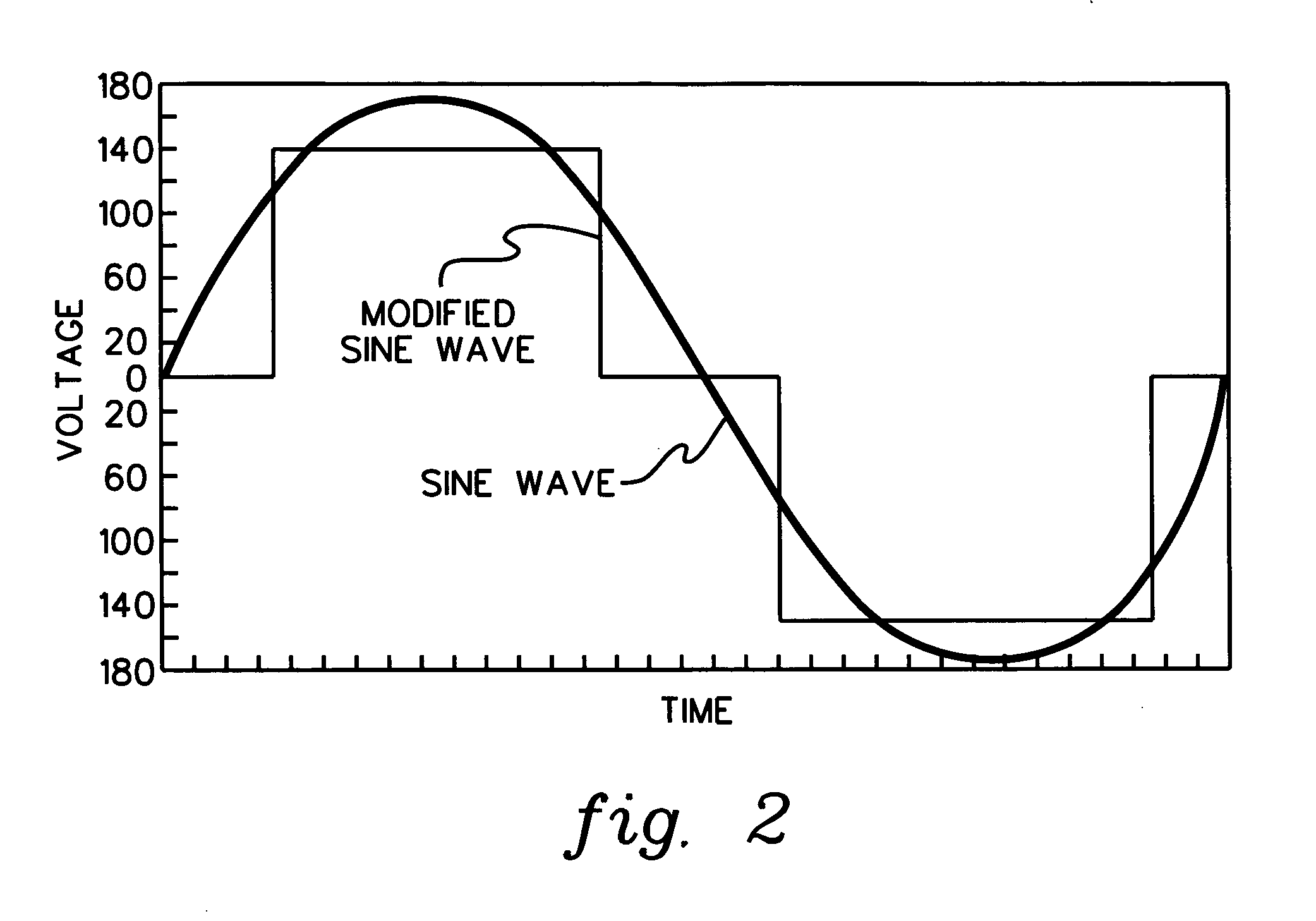
[0015] Generally stated, provided herein is a control scheme for a single phase AC induction motor, which is particularly advantageous for startup or shutdown transitioning of the motor. The control scheme includes driving the single phase motor using a drive signal of a first mode, which comprises one of a square wave mode (i.e., a modified sine wave or quasi sine wave mode) and a pulse width modulation mode. Responsive to a motor change command, the motor drive signal is transitioned from the first mode to a second mode, wherein the second mode comprises the other of the square wave mode and the pulse width modulation mode. The transitioning commences after motor frequency reaches a first centrifugal switch limit for the motor. The first centrifugal switch limit is a lower centrifugal switch limit when the first mode comprises the square wave mode, and is an upper centrifugal switch limit when the first mode comprises the pulse width modulation mode. The transitioning includes emp...


PUM


Abstract

A controller is provided for transitioning a drive signal to a single phase motor between a square wave and pulse width modulation modes, wherein the drive signal is in square wave mode at low motor frequencies and in pulse width modulation mode during normal operation. The transitioning includes using a real time motor model to effectuate transition of the drive signal between the modes, and a sampling rate for sampling the real time motor model during the transitioning. The sampling rate is automatically modified during the transitioning, wherein acceleration of the motor includes transitioning the drive signal from square wave mode to pulse width modulation mode, including periodically increasing the sampling rate during the transitioning. Conversely, when transitioning from pulse width modulation mode to square wave mode, the controller automatically deaccelerates the sampling rate during the transitioning.

Description

TECHNICAL FIELD [0001] The present invention relates generally to electronically commutated single phase motors, and more particularly to a method, system and program product for efficiently controlling operation of a single phase AC induction motor at startup or shutdown. BACKGROUND OF THE INVENTION [0002] Currently there are two principal types of power inverters. The first and simplest is called the “modified sine wave” or “square wave” inverter. With this topology, a 60 Hz square wave is used to drive the load directly, duty cycle adjusted to provide a desired RMS voltage (e.g., 120V RMS). This can be efficient since switching losses are almost nonexistent, with the devices being switched at the “low” line frequency. The second type of power inverter falls into two categories, filtered pulse width modulated (PWM) and non-filtered PWM. Filtered PWM is most applicable to single phase motor loads as the voltage is nearly a perfect sine wave. The problem with this approach is genera...

Claims


Application Information

Patent Timeline
Patent Type & Authority Applications(United States)
IPC IPC(8): H02P1/18H02P1/34H02P1/42H02P23/00H02P25/04
CPCH02P25/04H02P23/00
Inventor BIAMONTE, JEFFREY R.TRIFILO, TIMOTHY M.
Owner IBM CORP
Learn More