Device and method for active soundproofing, and power unit for aeroplanes

a technology of active soundproofing and power units, applied in the direction of sound producing devices, functional valve types, instruments, etc., can solve the problems of low sound level, low efficiency, and small space available for the installation of actuators, and achieve the effect of low noise, low cost and high efficiency

Inactive Publication Date: 2005-10-27
EADS DEUT GMBH
View PDF11 Cites 2 Cited by
  • Summary
  • Abstract
  • Description
  • Claims
  • Application Information

AI Technical Summary

Benefits of technology

[0009] Furthermore, in the state of the art, tones caused by subjecting cavities to flow are suppressed. Here, the sound is caused by instabilities in the flow. The cavities strongly excite these flows for certain frequencies, which results in very loud sounds. In order to suppress these tones and prevent the resulting sound, actuators are employed. By means of the actuators, resonance properties are influenced in such a way that the instability of the flow is not excited. Thus, the interaction of the instability with the resonance properties of the chamber is prevented.
[0038] Advantageously, the method of the invention is performed with the device of the invention. It is especially suited in the operation of an engine. Thereby the sound radiation of engines can be considerably reduced. The characteristics and advantages mentioned above in relation to the device, also apply to the method of the invention.

Problems solved by technology

The problem exists, however, that only very little space is available for the installation of the actuators, and the stator blades are moreover constructed very thin.
Furthermore, the sound levels produced are very low, due to the limited installation space available, so that only a very small portion of the primary sound field can be reduced.
That means that the production of high sound levels is almost impossible in acoustic actuators, since the size of the construction, weight and power consumption are too high for many applications.
When vibrating membranes which are driven by electromagnetic converters, such as electrodynamic converters or converters, which utilize the piezoelectric effect, are being used, the mechanical-acoustic degree of efficiency of the vibrating membranes is generally very low.
Therefore, in applications in which construction size, weight and power consumption are very restricted, high sound levels, which would be suitable for largely extinguishing a primary sound field, can barely be suitably generated with acoustic actuators or vibrating membranes.
Although these hybrid concepts or technologies do improve on the existing, purely passive concepts, nonetheless, no secondary sound field is generated, and no cancellation of sound is achieved.
The rods, however, do cause an interference in the inflow of the rotors, by means of which secondary sound is radiated from the rotor.
These types of constructions, however, do have a disadvantage, in that it is very difficult to adapt them to changes in the primary sound field, and they are consequently very inflexible.
Another disadvantage is the negative impact on the aerodynamics of the rotors, as well as significant problems in complying with safety criteria and safety regulations.
The cavities strongly excite these flows for certain frequencies, which results in very loud sounds.
Furthermore, an aircraft engine is to be created which is very silent in operation, whereby only very little installation space and low power supply have to be provided for active noise reduction.

Method used


Image

  • Device and method for active soundproofing, and power unit for aeroplanes
  • Device and method for active soundproofing, and power unit for aeroplanes

Examples


Embodiment Construction

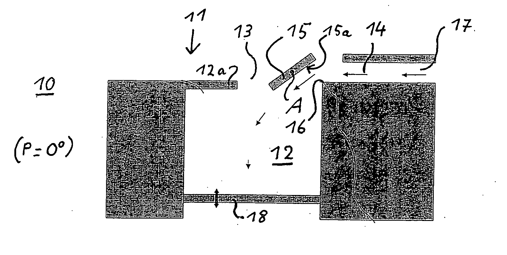
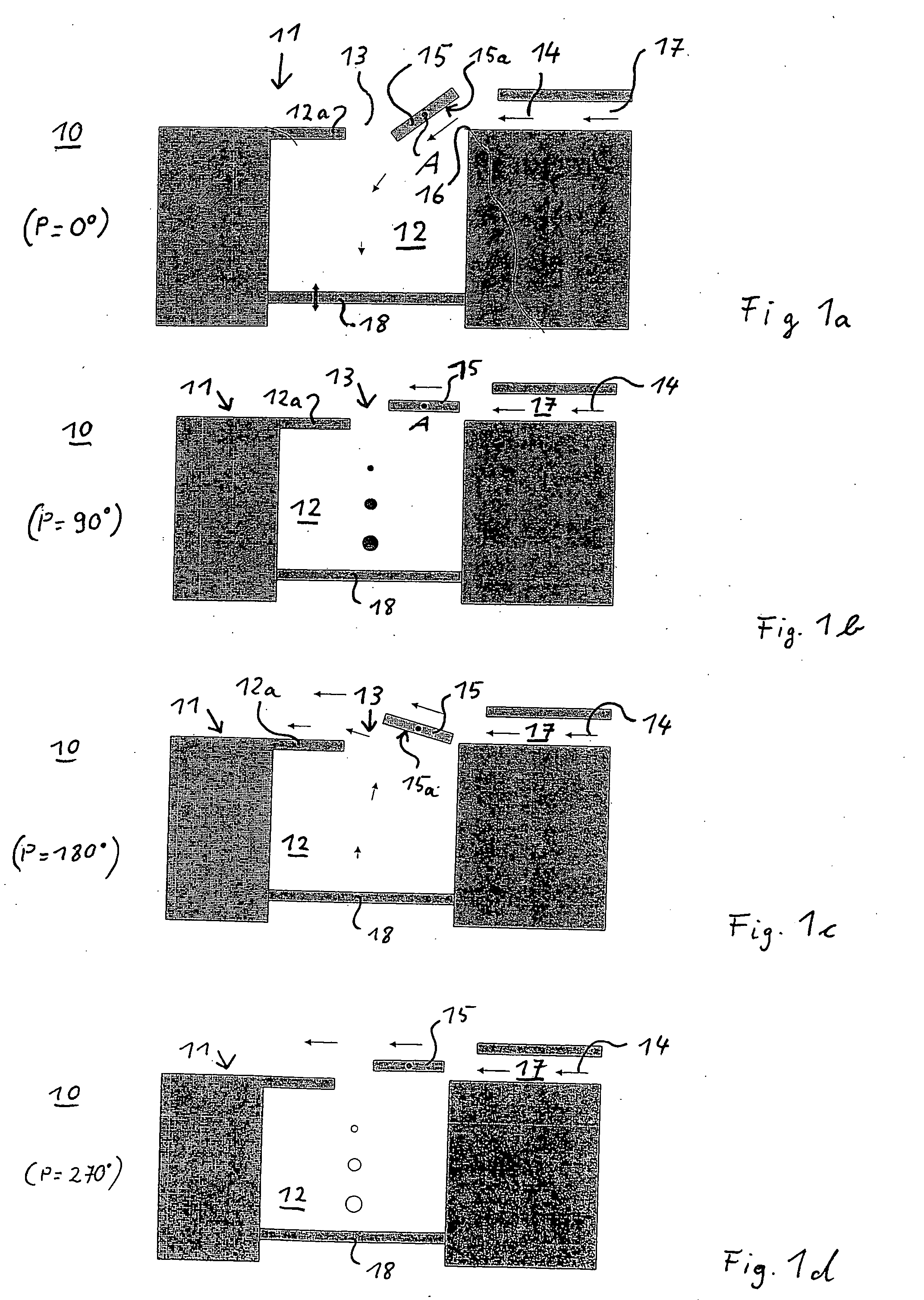
[0042]FIG. 1a shows a device 10 for sound absorption in a first operating phase. The device 10 consists of a housing 11, in whose interior a chamber 12 is constructed. The chamber 12 has a chamber opening 13 in a wall 12a, which is positioned on one side of the chamber 12, over which an air or gas flow 14 passes during operation. The wall 12a of the chamber 12, in which the chamber opening 13 is located, is aligned parallel to the direction of the gas flow 14 situated upstream of the chamber 12.

[0043] In the area of the chamber opening 13 a deflection device 15 is arranged, which has the form of a plate in the present example. The deflection device 15 is pivoted around an axis A, which is vertically oriented toward the direction of the thereto guided gas flow 14.

[0044] The plate-shaped deflection-device 15 may take various positions, which allow for the gas flow 14 to be at least partially directed into the chamber, or to direct the gas out of the chamber 12 towards the gas flow 1...


PUM


Abstract

A device (10) for active noise reduction consists of a chamber (12), which is arranged laterally in relation to a gas flow (14), whereby a chamber opening (13) is constructed in one wall of the chamber (12). In the area of the chamber opening (13) a deflection device (15) is adjustably arranged, whereby the deflection device (15), in a first position, at least partially directs the gas flow (14) running by the chamber opening (13) into the chamber (12), in order to compress air there, and, in a second position, directs the gas from the chamber (12) to the gas flow (14), in order to release the gas inside the chamber (12). The resulting alternating pressure inside the chamber (12) is radiated through the chamber opening (13) as sound and overlays the disturbing sound.

Description

BACKGROUND AND SUMMARY OF THE INVENTION [0001] The present invention relates to a device for active noise reduction, the use of such a device in an engine, especially an aircraft engine, a procedure for active noise reduction, and an engine for aircraft. [0002] The reduction of sound and the reduction of high sound levels are of increasing importance. Especially in the area of aircraft engines, measures for noise protection and noise reduction are required on a large scale for environmental reasons as well as for comfort. [0003] In particular, active noise reduction measures and hybrids are known in the state of the art. An active technology is for example described in the journal Aeroacoustics, Volume 1, Number 1, 2002, page 53. There, loudspeakers in the form of vibrating membranes are used to produce a secondary sound field, which cancels out the primary sound field. Moreover, the loudspeakers or actuators are arranged in the immediate vicinity of the source of the sound in the p...

Claims


Application Information

Patent Timeline
IPC IPC(8): F02C7/045F01D25/00G10K11/172
CPCG10K11/172
Inventor ZILLMANN, JOERGEN
Owner EADS DEUT GMBH
Why Eureka
Try Eureka