System and method for charge-balanced, continuous-write mask and wafer process for improved colinearity

a write mask and continuous write technology, applied in the manufacture of flux-sensitive heads, magnetic recording, thin film heads, etc., can solve the problems of insignificant contributor to the overall control of stripe height, image placement error, image placement error, etc., to maximize resolution and image edge fidelity, reduce write time, and small spot size

Inactive Publication Date: 2005-10-20
HITACHI GLOBAL STORAGE TECH NETHERLANDS BV
View PDF7 Cites 0 Cited by
  • Summary
  • Abstract
  • Description
  • Claims
  • Application Information

AI Technical Summary

Benefits of technology

[0015] By separating the critical and non-critical mask layers, steps can be taken to optimize each layer: one for colinearity and the other to minimize write time. Critical colinearity features are written at a very small spot size to maximize resolution and image edge fidelity. Non-critical mask features are written at large spot size to minimize write time. Total write time can be less than a single mask layer with a compromised spot size.
[0016] By separating critical and non-critical mask features into two mask layers, the critical colinearity features have such significant distance from each other that the stray electron beam problem is eliminated. In addition, with the separation of critical and non-critical mask features and the use of a reverse image design scheme that defines the upper and lower stripe edges in a negative mask format, an entire set of critical features can be written in less than an hour instead of many hours. This is a first step toward reducing error due to glass expansion or shrinkage, and control of stray E-beam problems, which will substantially improve colinearity.
[0017] Next, by separating critical and non-critical mask features and using a reverse image design scheme, glass expansion error can be effectively eliminated by writing each row continuously starting with the MR stripe in the first column to the MR stripe in the last column of each row. This system writes each row in less than two minutes to further reduce the errors related to glass expansion or shrinkage.
[0018] Furthermore, by separating critical and non-critical mask features and using the reverse image design scheme with continuous write, other mechanical effects associated with long y-axis stage moves are eliminated and data can be organized to write in unfractured images. Eliminating long stage moves reduces image placement error that further reduces colinearity error. Writing unfractured images eliminates the tools' minimum data segment boundary problem and achieves a more accurate position of critical features through improved mask registration.
[0019] Moreover, by separating critical and non-critical mask features, using the reverse image design scheme with continuous write, and adding additional charge-balancing features, colinearity error associated with unbalanced photo-resist charging is eliminated. These charge-balancing features, written before the critical features are written, purposely add equal electron charge above and below the critical images to prevent electron beam deflection by unequal electron charge that would otherwise exist.

Problems solved by technology

Historically, glass masks made by E-beam and laser mask tools had such high quality that they were an insignificant contributor to the overall control of stripe height.
However, as aerial densities in disk drives increase, the need for narrower track widths and shorter stripe heights requiring tighter controls have made mask colinearity a significant detractor in achieving satisfactory stripe height requirements.
The problems associated with improving colinearity include a number of errors associated with the control of image size, image placement, and image edge fidelity, namely: 1.
Positional error of the stage mechanics relative to a Cartesian grid contributes to image placement error; 2.
Glass expansion during the time that it takes to write a row of stripe images contributes to image placement error; 3.
Variation in the electron charging of the photo-resist can unevenly deflect the E-beam during the writing of critical edges, thereby contributing to image placement error; 4.
Image error by stray E-beams during the writing of adjacent non-critical images or structures can affect the exposure of critical images resulting in a variation in optimum development time from image to image, thereby increasing colinearity error; and 6.
Where it would be desirable to write at very small spot sizes for highest resolution and accuracy, it is not practical to do so because of long write time.
All of these problems contribute to error in image placement, image size, or image edge fidelity, which in turn increases colinearity error.
However, laser-generated masks may show superior colinearity results if continuous write methods were employed.

Method used


Image

  • System and method for charge-balanced, continuous-write mask and wafer process for improved colinearity
  • System and method for charge-balanced, continuous-write mask and wafer process for improved colinearity
  • System and method for charge-balanced, continuous-write mask and wafer process for improved colinearity

Examples


Embodiment Construction

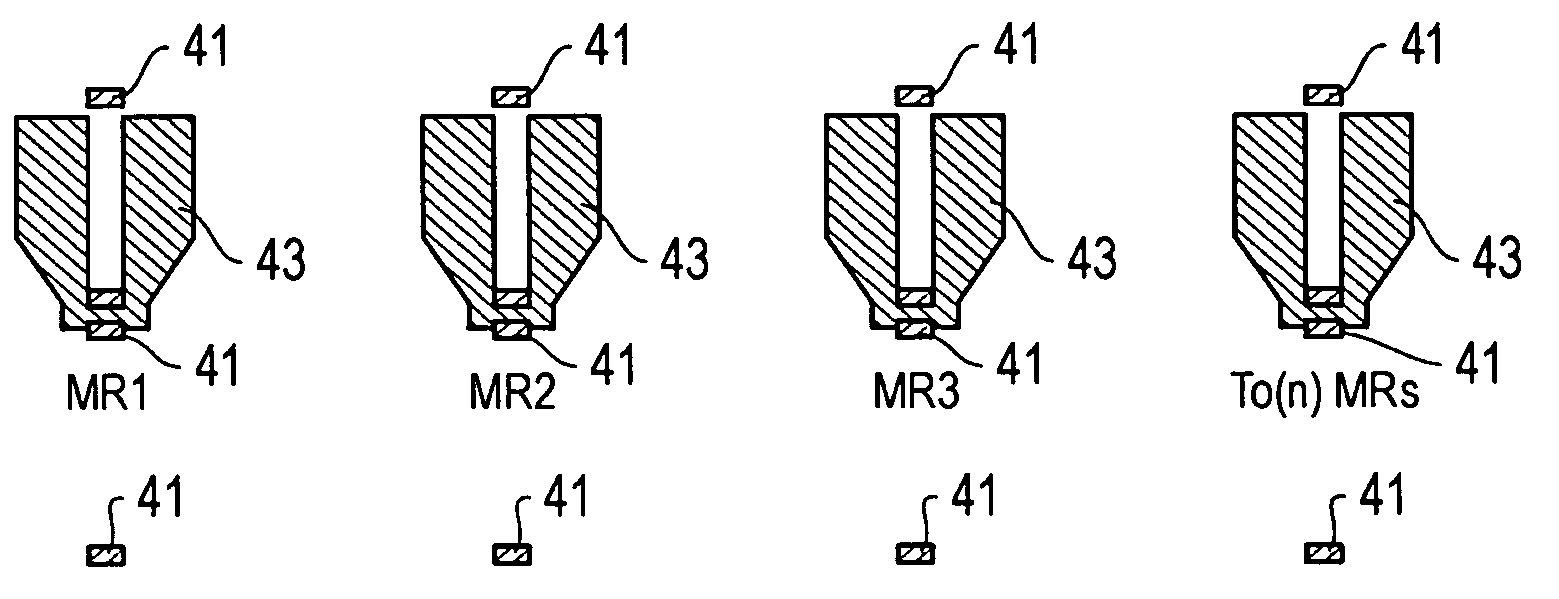
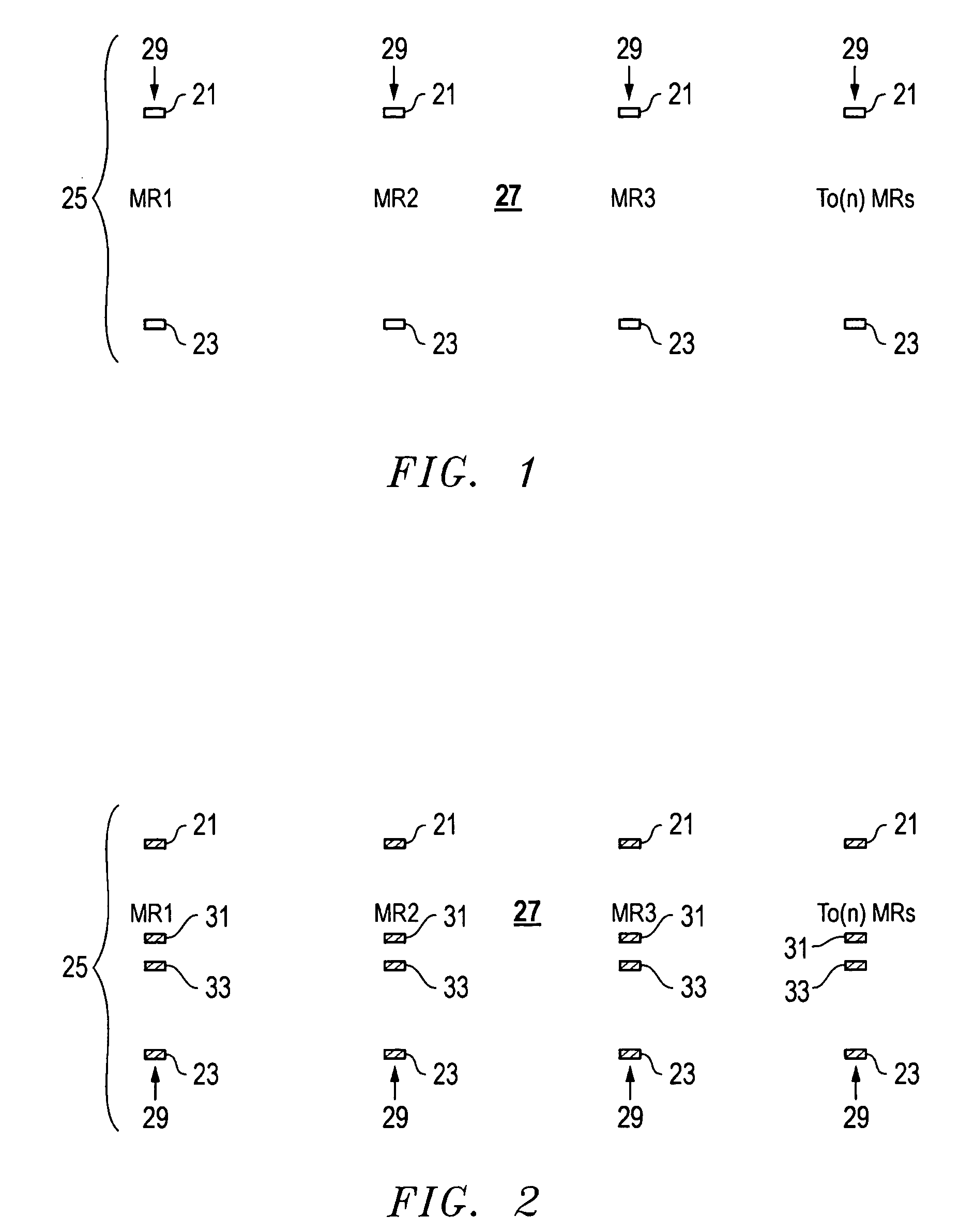
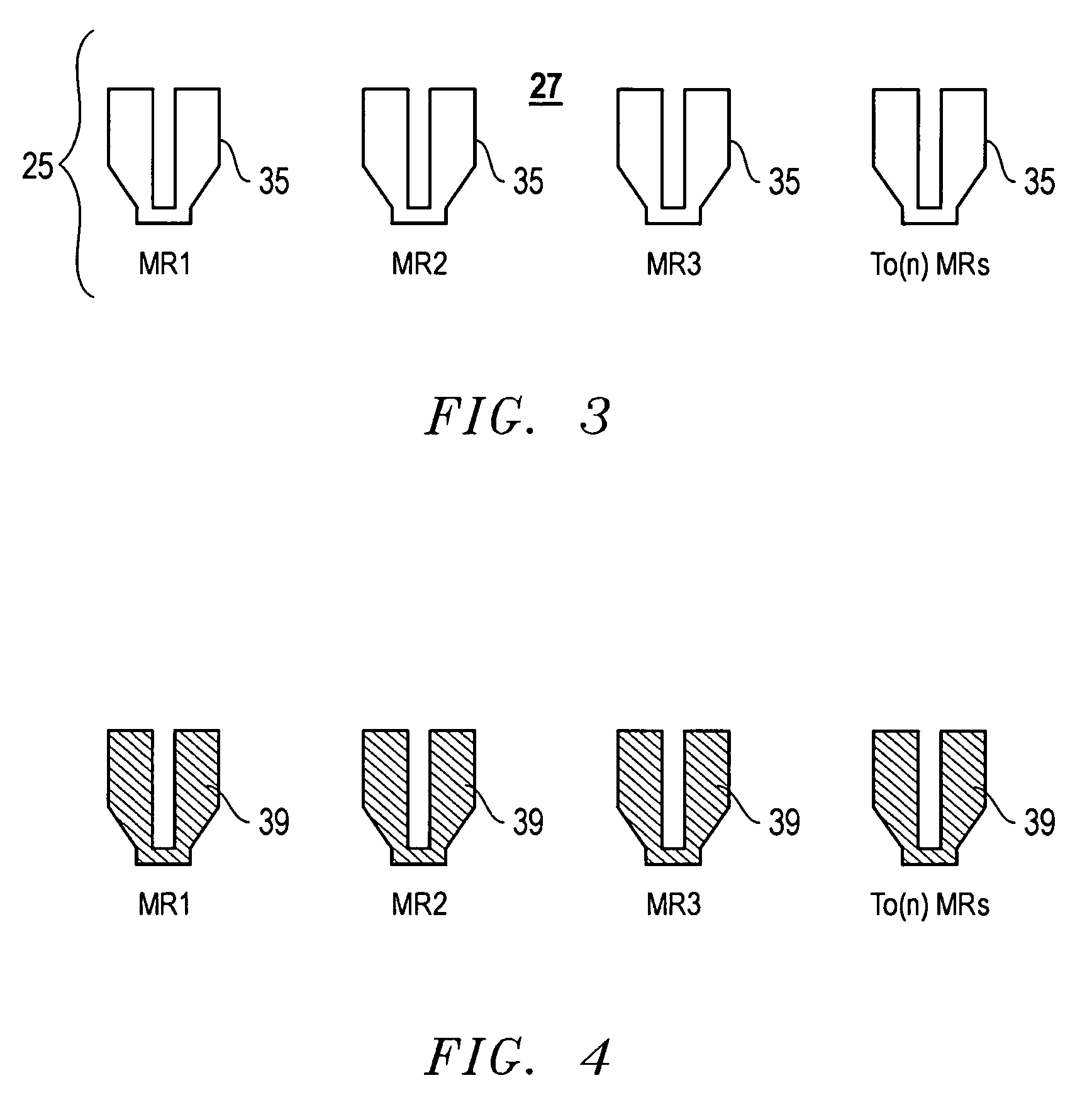
[0032] Referring to FIGS. 1-10, one embodiment of a system and method for a charge-balanced, continuous write mask and wafer process is shown. The first step is to write “charge-balancing” features 21, 23 in order to build a critical negative image magneto resistive (MR) stripe defining field. In this disclosure, although a single mask background and foreground is preferred, a double mask may be used. The system of the present invention has several fields, including foreground in one, test sites in continuous write mode in another, background non-critical targets in another, critical targets in another, etc.

[0033] In the prior art, design systems required designers to design in correct positive, correct negative, reverse positive, reverse negative format considering the use of negative or positive photo-resist. Thereafter the post-processing programs are given instructions to write as correct positive, correct negative, reverse positive, and reverse negative depending on what is wa...


PUM

PropertyMeasurementUnit
charge-aaaaaaaaaa
charge-balancingaaaaaaaaaa
sizeaaaaaaaaaa

Abstract

A charge-balanced, continuous-write mask and wafer process changes the magneto resistive photo-definition step to a two-mask step operation. Critical images are written on one mask layer at a very small electron beam spot size, and non-critical images are written on a second mask layer at a relatively larger electron beam spot size. Both mask layers are put onto the same glass substrate where the critical mask layer is located at the most accurate position on the substrate. The non-critical images may be placed in a peripheral field. In wafer processing, the critical field is aligned and exposed onto the wafer and then the non-critical field is aligned and exposed.

Description

BACKGROUND OF THE INVENTION [0001] 1. Technical Field [0002] The present invention relates in general to an improved write mask and wafer process and, in particular, to an improved system and method for a charge-balanced, continuous-write mask and wafer process. [0003] 2. Description of the Related Art [0004] Glass masks are used in magneto resistive (MR) thin film head wafer processes. Electron beam (E-beam) or laser photo-resist imaging tools are used in the production of such glass masks. Specific mask layers typically have critical overlay and image size tolerances. The critical masks used for the MR stripe layer have an additional requirement known as colinearity error, which is defined as the y-axis deviation of the back edge of a row of MR stripes from a straight line. The colinearity quality is important because it directly relates to a key magnetic performance parameter known as MR stripe height. [0005] Historically, glass masks made by E-beam and laser mask tools had such ...

Claims


Application Information

Patent Timeline
Patent Type & Authority Applications(United States)
IPC IPC(8): G03F7/20G06F17/50G11B5/31G11B5/39
CPCG03F1/78G11B5/3903G11B5/3163G03F7/2063
Inventor ALMES, ROBIN LYNNCHURCH, MARK ANTHONYGUTBERLET, MARY KATHRYNTSAY, JIUNNWANG, BENJAMIN LU CHEN
Owner HITACHI GLOBAL STORAGE TECH NETHERLANDS BV
Why Eureka
Try Eureka