Anisotropic conductive sheet and its manufacturing method

a technology manufacturing method, which is applied in the direction of elastomeric connection elements, connection contact material, coupling device connection, etc., can solve the problems of anisotropic conductive film not keeping its function to a sufficient degree, and it is difficult to shorten the distance between such thin metal wires, and achieves the effect of suitable contact pressur

Inactive Publication Date: 2005-10-20
JST MFG CO LTD
View PDF5 Cites 11 Cited by
  • Summary
  • Abstract
  • Description
  • Claims
  • Application Information

AI Technical Summary

Benefits of technology

[0035] In the anisotropic conductive sheet according to the present invention, the conductive piece may protrude compared to the nonconductive matrix. “Protruding” refers to a case where the portion of the conductive piece is thicker than the portion of the nonconductive matrix in the thickness of the anisotropic conductive sheet, a case where the position of the upper surface of the nonconductive matrix is lower than that of the upper surface of the conductive piece when the anisotropic conductive sheet is horizontally placed, and / or a case where the position of the lower surface of the nonconductive matrix is higher than that of the lower surface of the conductive piece when the anisotropic conductive sheet is horizontally placed. With such configurations, the electric contact of the electronic parts and that of the terminals of the substrate become more reliable. This is because the terminals, first, come in contact with the conductive pieces as they approach the sheet, and a suitable degree of contact pressure is secured due to the pushing force to the sheet.

Problems solved by technology

In the anisotropic conductive film with thin metal wires, however, it is difficult to shorten distance between such thin metal wires and to secure anisotropic conductivity with a fine pitch as required by recent highly integrated circuit boards and electronic components.
Further, it is likely that thin metal wires are to be buckled with compressive force or the like during the use thereof and easily pulled out after repetitive use so that the anisotropic conductive film may fail to keep its function to a sufficient degree.

Method used


Image

  • Anisotropic conductive sheet and its manufacturing method
  • Anisotropic conductive sheet and its manufacturing method
  • Anisotropic conductive sheet and its manufacturing method

Examples


Embodiment Construction

[0053] Hereinafter the present invention will be described in more detail by way of embodiments with reference to the drawings. However, the embodiments are simply to illustrate specific materials and numerical values as preferred examples of the invention, but are not to limit the invention.

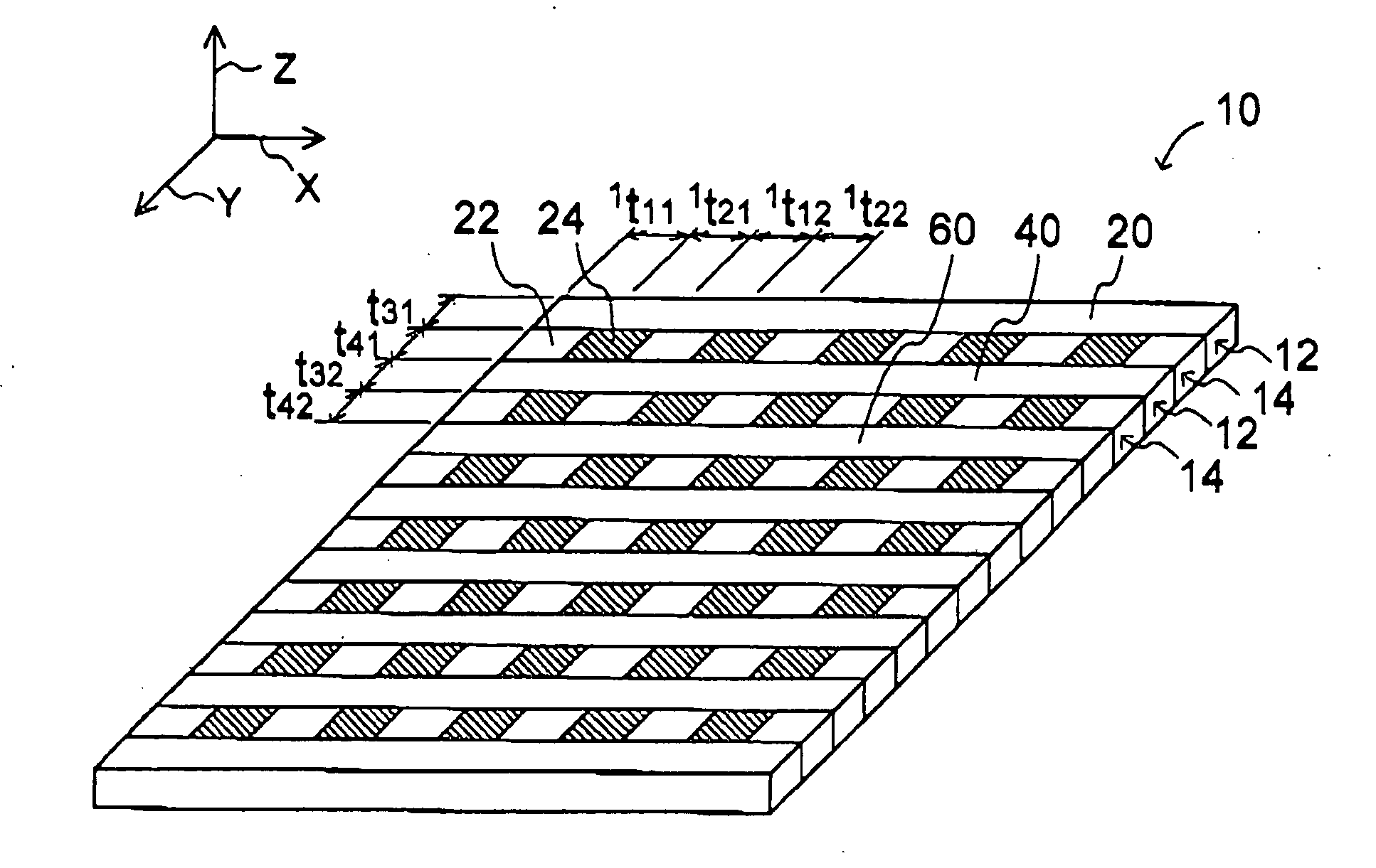
[0054]FIG. 1 illustrates an anisotropic conductive sheet 10 according to an embodiment of the present invention. A Cartesian coordinate system XYZ of the anisotropic conductive sheet 10 is illustrated at a left upper part (the same also holds in FIG. 2). The anisotropic conductive sheet 10 of this embodiment is a rectangular sheet member in which there are alternately arranged nonconductive strip-like members 12 and strip-like members 14 of a striped pattern having conductive pieces and nonconductive pieces that are alternately arranged. The neighboring nonconductive strip-like members 12 and strip-like members 14 of the striped pattern are coupled together using a coupling agent. In the anisot...


PUM


Abstract

The present invention relates to an anisotropic conductive sheet, which is interposed between a circuit board such as a substrate and various circuit parts to render conductive paths and a manufacturing method thereof, providing the anisotropic conductive sheet securing a fine pitch anisotropic conductivity required by the recent highly integrated circuit boards and electronic parts yet keeping high durability of the conductive member. The anisotropic conductive sheet (10) is constituted by alternately arranging strip-like members (14) of a striped pattern having conductive pieces (24) and nonconductive pieces (22) alternately arranged, and nonconductive strip-like members (12).

Description

FIELD OF THE INVENTION [0001] The present invention relates to an anisotropic conductive sheet, which is interposed between a circuit board such as a substrate and various circuit devices (components) to render conductive path, and to its manufacturing method. RELATED ART [0002] As recent electronic devices become smaller and thinner, there has been more and more increased necessity of connections between circuits of fine patterns and between a minute portion and a circuit of fine patterns. As a connecting method, there are used the solder junction technology and anisotropic conductive adhesives. There is further employed a method of interposing an anisotropic conductive elastomer sheet between electronic components and a circuit board to render a conductive path. [0003] The anisotropic conductive elastomer sheet refers to an elastomer sheet that is conductive only in a specific direction. Generally, there are anisotropic conductive elastomer sheets, which are conductive in only the...

Claims


Application Information

Patent Timeline
Patent Type & Authority Applications(United States)
IPC IPC(8): H01R13/24H01R43/00
CPCH01R13/2414H01R12/714H01R43/007H01R11/01
Inventor HASEGAWA, MIKI
Owner JST MFG CO LTD
Why Eureka
Try Eureka