
Microfluidic test device

Active Publication Date: 2005-10-20
LEADWAY HK
View PDF71 Cites 107 Cited by
  • Summary
  • Abstract
  • Description
  • Claims
  • Application Information

AI Technical Summary

Benefits of technology

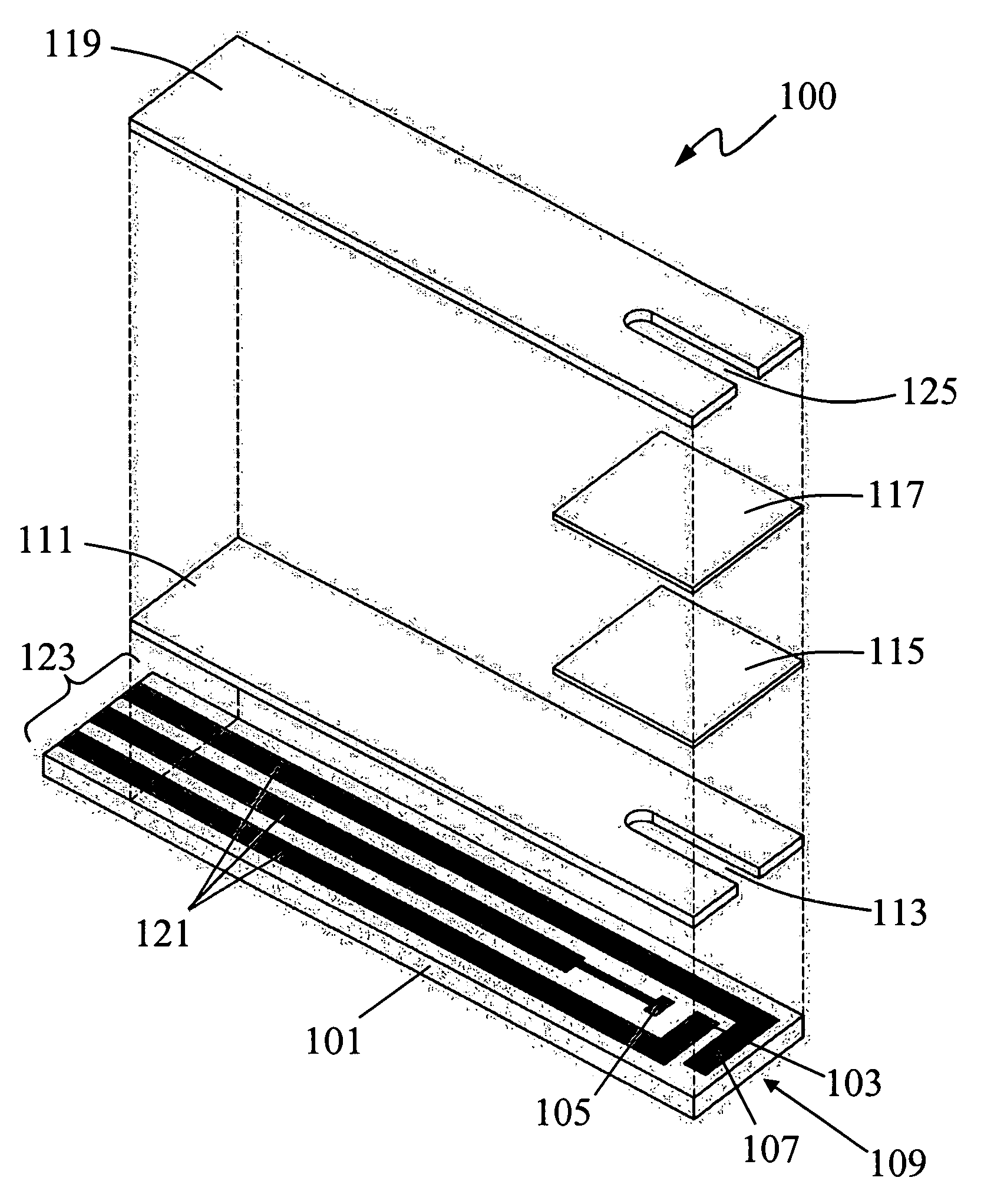
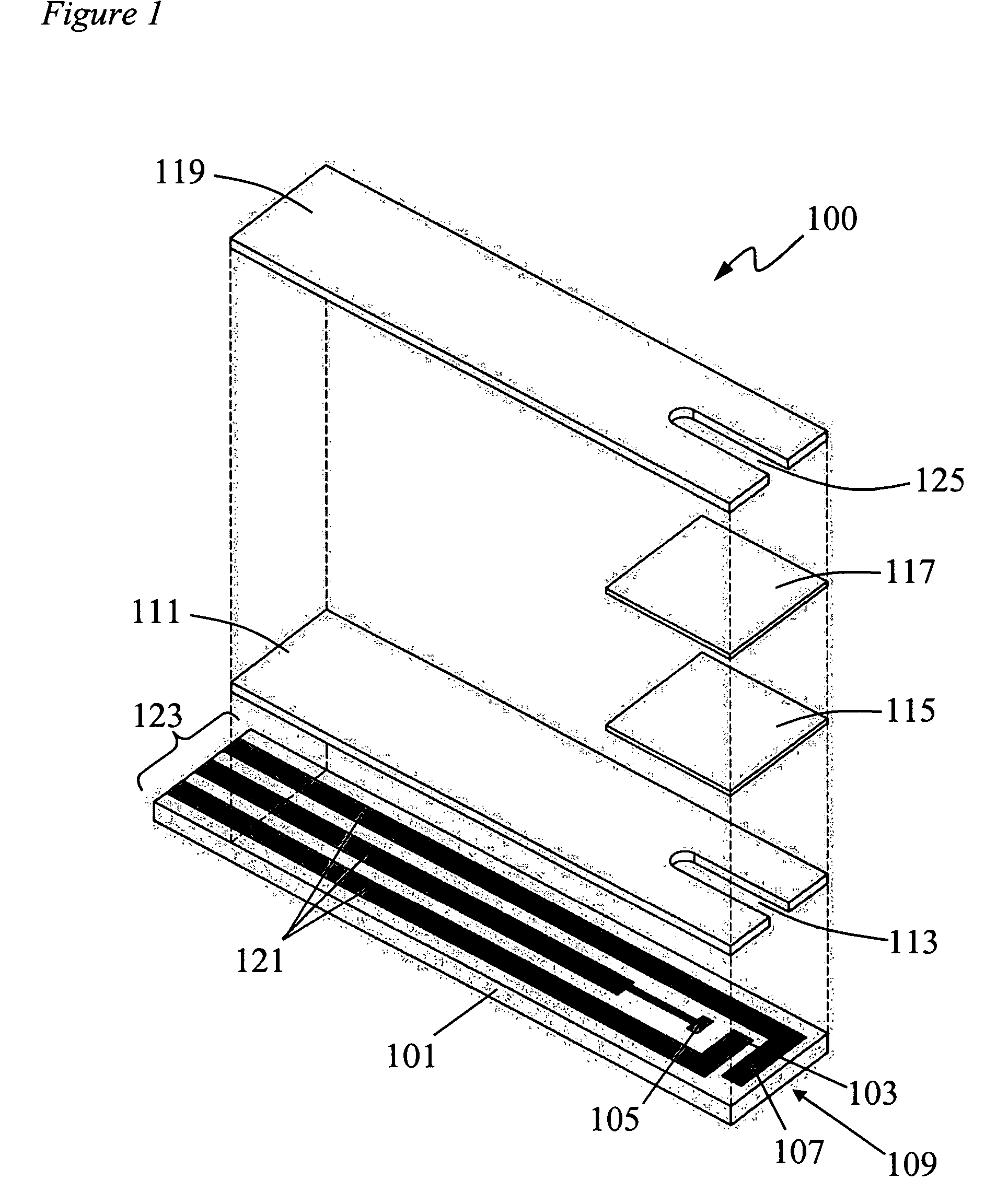
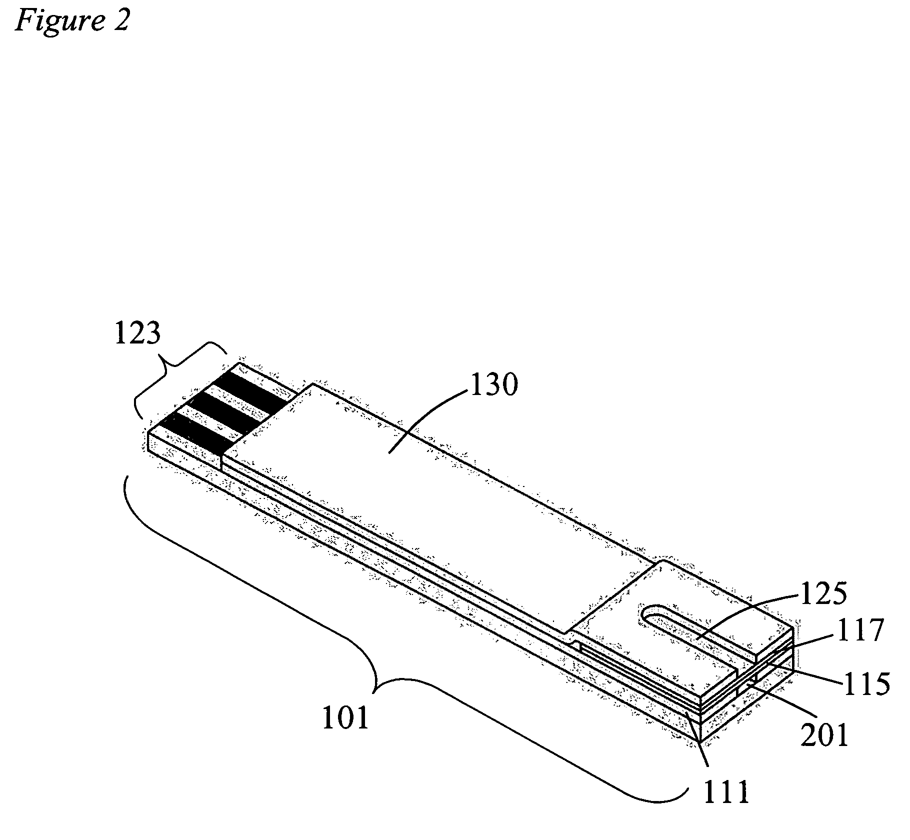
[0008] The present invention provides test devices for measuring the presence or amount of an analyte in a biological fluid. The test devices contain material components, which are assembled to form the device. These devices require a minimum of sample volume, and can be used to accurately determine the quantity of an analyte in a fluid sample. The devices have a base plate that has an electrode system embedded therein, and a hydrophilic porous material situated on the base plate. A hydrophobic protective layer is situated on the hydrophilic porous material, and a cover is placed on the hydrophobic protective layer. In one embodiment the protective layer is porous and allows for the passage of air from the reaction chamber to the exterior of the device. Some embodiments also use an insulating layer, which can be situated between the base la

Problems solved by technology

In spite of the advances achieved in rapid and accurate measurement of metabolites, patient compliance remains a significant problem due to the pain associated with blood withdrawal.
However, there are also fewer surface blood vessels, which make it difficult to obtain enough blood for the test.
This is a problem because prior art biosensors require several microliters of blood to correctly fill the capillary channel and function.
If the volume of sample is too low, the capillary channel will not fill properly.
The test will either not work or will give inaccurate results.
This situation is very difficult and upsetting for some patients and reduces their compliance in blood monitoring.
Consequently, these patients have difficulty monitoring and correctly treating their disease.

Method used


Image

  • Microfluidic test device
  • Microfluidic test device
  • Microfluidic test device

Examples


example 1

Construction of a Sensor

[0046] This example illustrates the construction of a sensor of the invention. A 14 mil chip of print-treated PET was selected to form the base plate. Ag / AgCl ink was printed onto the PET base to form the contact leads, conductive leads, and reference electrode of the electrode system, followed by heating to dry. Conductive carbon ink was then printed to form the conductive leads, contacts, counter and working electrodes of the electrode system, followed by heating to dry (FIG. 1). A PET insulating layer sandwiched with acrylic pressure sensitive adhesive (PSA) and silicone release layers on both sides was laser cut to form the insulating layer 111. By peeling away one side of the release layer, the pressure sensitive adhesive (PSA) PET insulating layer was superimposed onto the base plate having the conductive electrodes. Optionally, the PSA PET can be replaced with a screen printed carbon insulating layer having the groove 113. Peeling away another release...

example 2

[0048] This example illustrates a use of the invention in the detection of blood glucose levels. A device was manufactured as described in Example 1 containing a dried reagent present in the reaction chamber and having the following components: a phosphate buffer solution in which is dissolved at least one hydrophilic polymer such as cellulose, a low disaccharide trehalose stabilizer, a Triton X-100 surfactant, a ferricyanide mediator and glucose oxidase enzyme. This reagent was selected to test for the presence and quantity of glucose in whole blood.

[0049] A three electrode system was used in this embodiment and the reagent film covered all three electrodes. It is estimated that when sample is applied to the sensor, it will be brought into contact with all three electrodes within 1 second. The hydrophobic protective layer served to prevent contamination of the sample with sweat or oils from the operator's hands.

[0050] The sensor was inserted into the insertion port of a VMP Poten...


PUM

PropertyMeasurementUnit
Electrical conductoraaaaaaaaaa
Hydrophilicityaaaaaaaaaa
Hydrophobicityaaaaaaaaaa

Abstract

The present invention provides biosensor test devices for measuring the presence or amount of an analyte in a biological fluid. The devices have a base plate that has an electrode system embedded therein, and a hydrophilic porous material situated on the base plate. A hydrophobic protective layer is situated on the hydrophilic porous material, and a cover is placed on the hydrophobic protective layer to complete the device. Some embodiments also use an insulating layer, which can be situated between the base layer and the hydrophilic porous material. The cover of the device has an opening present therein, situated over the electrodes, so that the electrodes communicate with the exterior of the device through the groove. The insulating layer can also have a groove situated therein, which in one embodiment is placed to align with the groove in the cover. The invention also provides methods of manufacturing the devices, and methods of using them.

Description

[0001] This application claims priority to U.S. provisional patent application Ser. No. 60 / 547,274, filed Feb. 23, 2004, which is hereby incorporated by reference in its entirety, including all tables, figures, and claims.FIELD OF THE INVENTION [0002] The present invention relates to biosensors having improved sample application and measuring properties and methods of their manufacture and use. BACKGROUND OF THE INVENTION [0003] The following Background of the Invention is intended to aid the reader in understanding the invention and is not admitted to be prior art. [0004] In recent years, medical care has changed dramatically, from primarily using clinical laboratory analysis of samples to rapid point of care testing in the doctor's office or at the patient's bedside. Disposable enzyme biosensors are frequently used to perform these rapid tests. Taking glucose testing as an example, in-home testing by the patient is now commonplace and a necessity for proper disease management. To ...

Claims


Application Information

Patent Timeline
IPC IPC(8): B01L3/00C12Q1/00G01N27/27G01N27/30G01N33/487G01N33/543
CPCB01L3/5023G01N27/3272G01N33/5438C12Q1/006
Inventor TSAI, FU HSIUNGLIN, JINN-NANWANG, CHIA-LIN
Owner LEADWAY HK
Learn More