
Electrospinning in a controlled gaseous environment

a gaseous environment and control technology, applied in the field of electropinning fibers, can solve the problems of limited application of nano-fibers, difficult large-scale production of nano-fibers, and solvent volatilization in small spaces

Active Publication Date: 2005-10-13
RES TRIANGLE INST
View PDF65 Cites 62 Cited by
  • Summary
  • Abstract
  • Description
  • Claims
  • Application Information

AI Technical Summary

Benefits of technology

The present invention provides an apparatus and method for improving the process window for production of electrospun fibers. The apparatus includes an extrusion element, a collector, and a chamber enclosing the extrusion element and the collector, and a control mechanism for controlling the gaseous environment in which the fibers are to be electrospun. The method includes applying an electric field to the extrusion element, controlling the gaseous environment, and electrospinning the substance from the tip of the extrusion element by an electric field extraction of the substance from the tip into the controlled gaseous environment. The invention promotes the electrospinning process by introducing charge carriers into the gaseous environment and controlling the drying rate of the electrospun fibers by controlling the solvent pressure in the gaseous environment. The technical effects include improved process window, controlled gaseous environment, and promotion of the electrospinning process.

Problems solved by technology

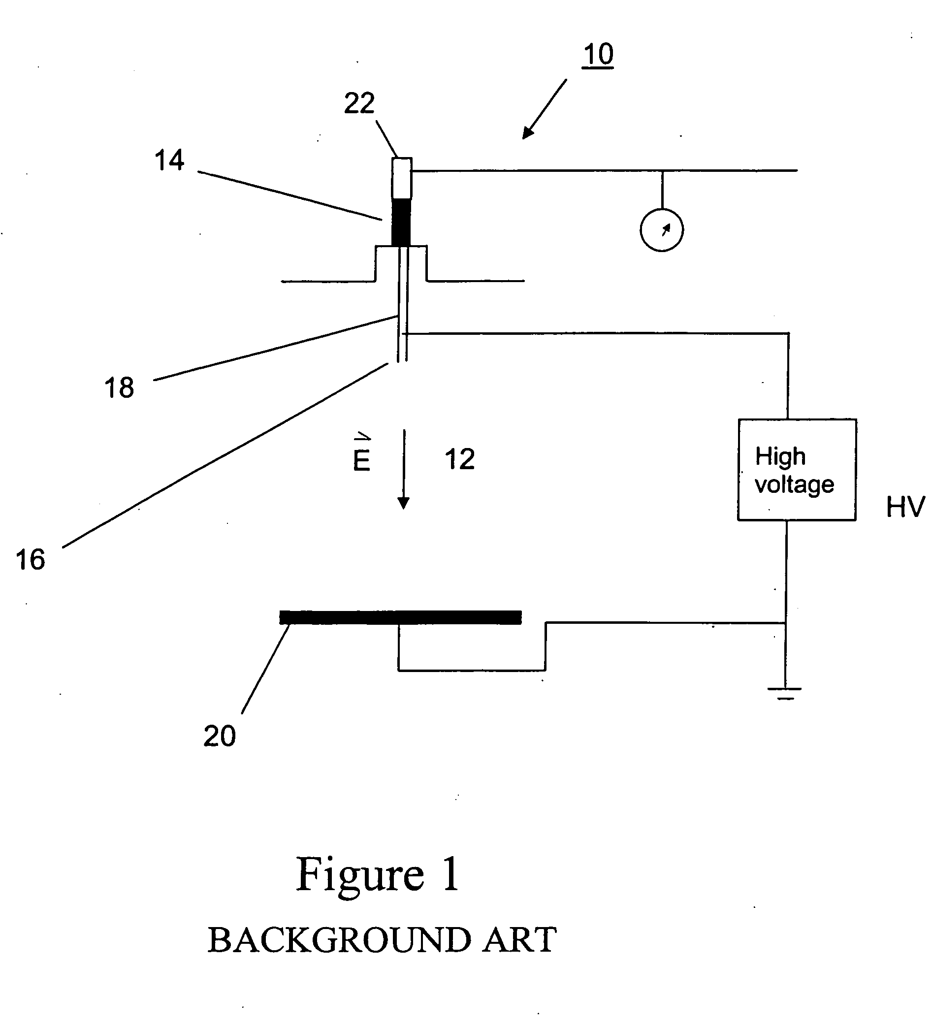
Publication No. 2002 / 0100725 A1 describes, besides the solvents and materials used for nanofibers, the difficulties of large scale production of the nanofibers including the volatilization of solvents in small spaces.
Despite the advances in the art, the application of nano-fibers has been limited due to the narrow range of processing conditions over which the nano-fibers can be produced.

Method used


Image

  • Electrospinning in a controlled gaseous environment
  • Electrospinning in a controlled gaseous environment
  • Electrospinning in a controlled gaseous environment

Examples


Embodiment Construction

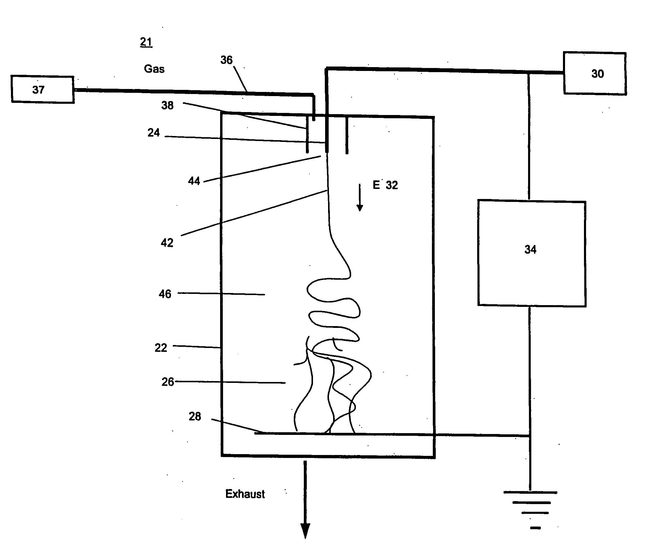
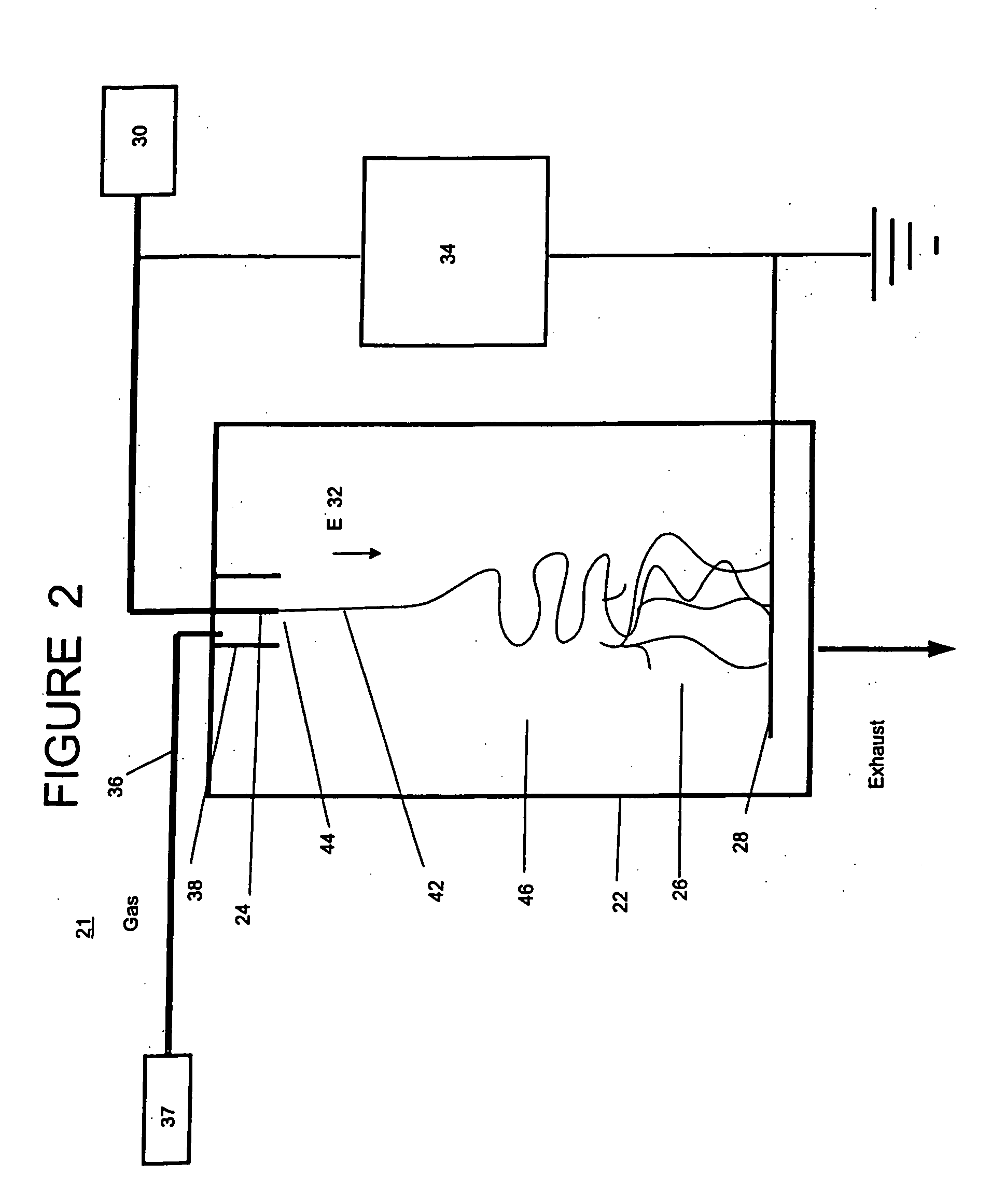
[0026] Referring now to the drawings, wherein like reference numerals designate identical, or corresponding parts throughout the several views, and more particularly to FIG. 2, FIG. 2 is a schematic illustration of an electrospinning apparatus 21 according to one embodiment the present invention in which a chamber 22 surrounds an electrospinning extrusion element 24. As such, the extrusion element 24 is configured to electrospin a substance from which fibers are composed to form fibers 26. The electrospinning apparatus 21 includes a collector 28 disposed from the extrusion element 24 and configured to collect the fibers. The chamber 22 about the extrusion element 24 is configured to inject charge carriers, such as for example electronegative gases, ions, and / or radioisotopes, into a gaseous environment in which the fibers 26 are electrospun. As to be discussed later, injection of the charge carriers into the gaseous environment in which the fibers 26 are electrospun broadens the pro...


PUM

PropertyMeasurementUnit
temperatureaaaaaaaaaa
electric fieldaaaaaaaaaa
areaaaaaaaaaaa

Abstract

Apparatus and method for producing fibrous materials in which the apparatus includes an extrusion element configured to electrospin a substance from which the fibers are to be composed by an electric field extraction of the substance from a tip of the extrusion element, a collector disposed from the extrusion element and configured to collect the fibers, a chamber enclosing the collector and the extrusion element, and a control mechanism configured to control a gaseous environment in which the fibers are to be electrospun. The method includes providing a substance from which the fibers are to be composed to a tip of an extrusion element, applying an electric field to the extrusion element in a direction of the tip, controlling a gaseous environment about where the fibers are to be electrospun, and electrospinning the substance from the tip of the extrusion element by an electric field extraction of the substance from the tip into the controlled gaseous environment.

Description

CROSS REFERENCE TO RELATED APPLICATIONS [0001] This application is related to U.S. application Ser. No. ______ filed on ______, entitled “Electrospinning of Polymer Nanofibers Using a Rotating Spray Head,” Attorney Docket No. 241015US-2025-2025-20, the entire contents of which are incorporated herein by reference. This application is also related to U.S. application Ser. No. ______, filed on ______, entitled “Electrospraying / electrospinning Apparatus and Method,” Attorney Docket No. 241013US-2025-2025-20, the entire contents of which are incorporated herein by reference.STATEMENT REGARDING FEDERALLY SPONSORED RESEARCH [0002] The U.S. Government, by the following contract, may have a paid-up license in this invention and the right in limited circumstances to require the patent owner to license others on reasonable terms, as provided for by the terms of DARPA Contract No. 972-01-C-0058.DISCUSSION OF THE BACKGROUND [0003] 1. Field of the Invention [0004] This invention relates to the f...

Claims


Application Information

Patent Timeline
Patent Type & Authority Applications(United States)
IPC IPC(8): D01D5/00D01F9/14H05B6/00H05B6/62
CPCD01D5/0061D01F11/00H05B6/62Y10T428/249924Y10T428/2913D01D5/00D01F9/14
Inventor ANDRADY, ANTHONY L.ENSOR, DAVID S.
Owner RES TRIANGLE INST
Learn More