
Multi-gate MOS transistor and method of manufacturing the same

Active Publication Date: 2005-10-13
ELECTRONICS & TELECOMM RES INST
View PDF6 Cites 36 Cited by
  • Summary
  • Abstract
  • Description
  • Claims
  • Application Information

AI Technical Summary

Benefits of technology

[0011] The present invention is directed to a multi-gate MOS transistor having an increased channel width in order to increase current driving capability and a method of manufacturing the same.

Problems solved by technology

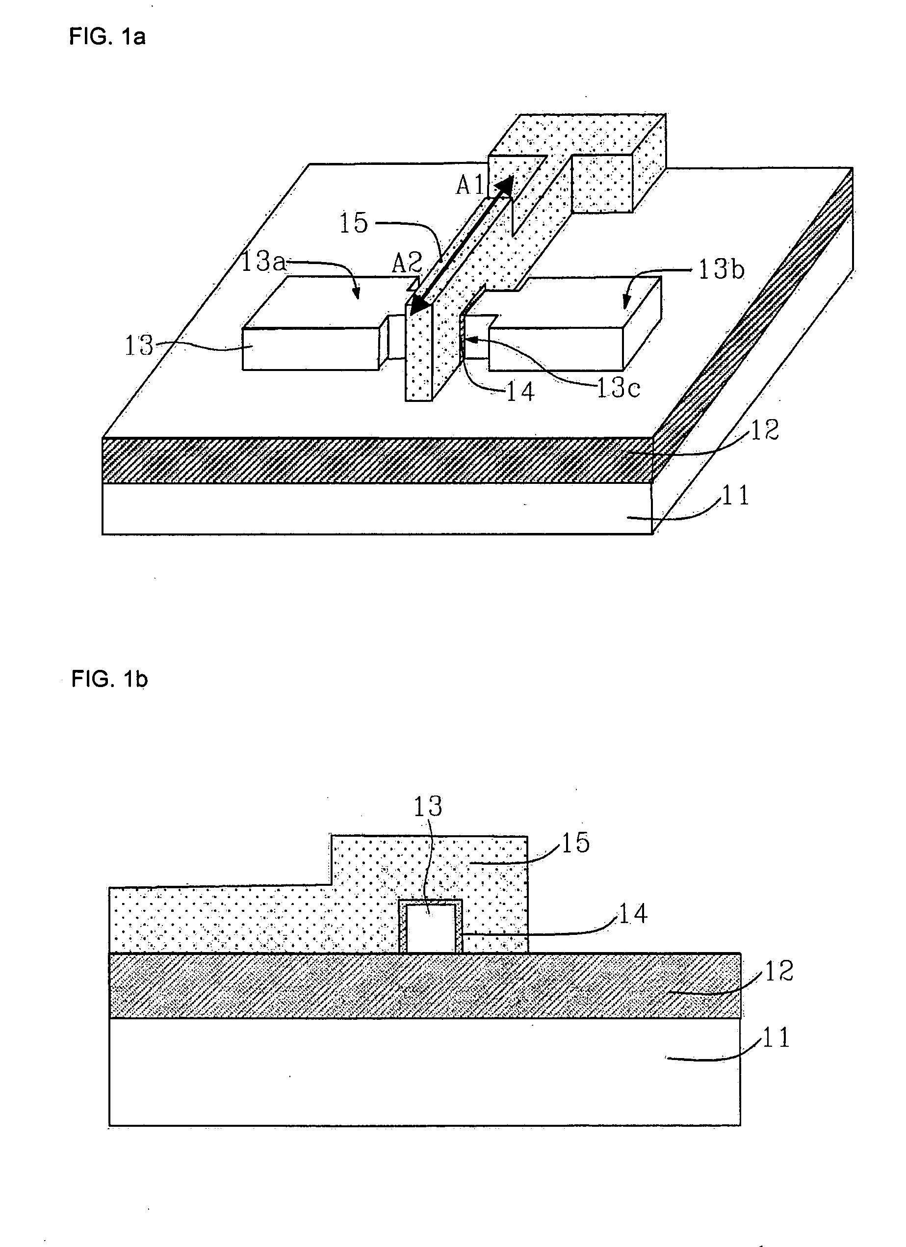
As a MOSFET has also undergone a continuous size reduction, a problem regarding reliability such as a short channel effect is being caused.
As described above, the conventional tri-gate FinFET has a structural limitation in increasing the drain current.
As a result, there is a limitation in obtaining current driving capability per unit area in terms of integration.

Method used


Image

  • Multi-gate MOS transistor and method of manufacturing the same
  • Multi-gate MOS transistor and method of manufacturing the same
  • Multi-gate MOS transistor and method of manufacturing the same

Examples


Embodiment Construction

[0024] Reference will now be made in detail to the embodiments of the present invention, examples of which are illustrated in the accompanying drawings, wherein like reference numerals refer to the like elements throughout. The embodiments are described below in order to explain the present invention by referring to the figures.

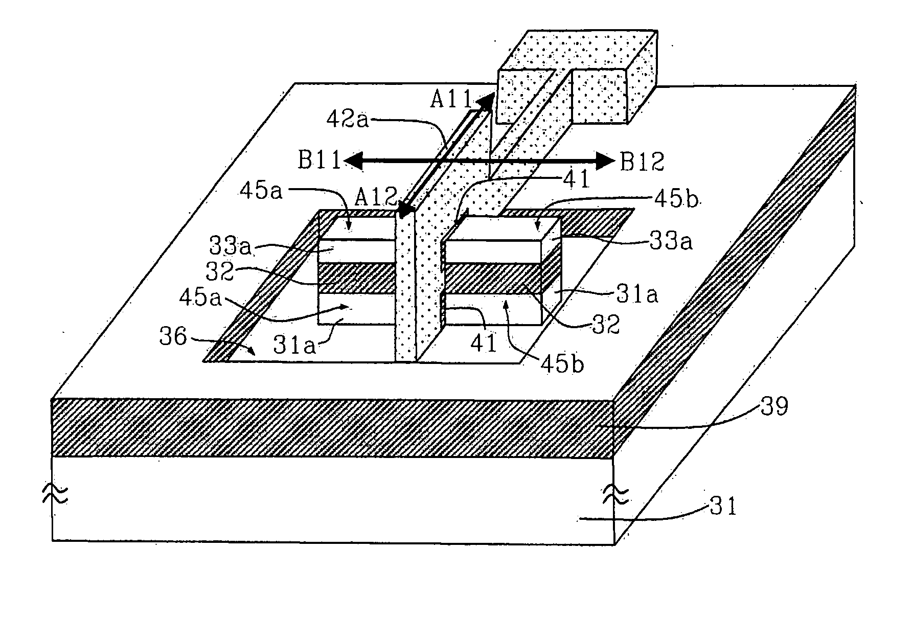
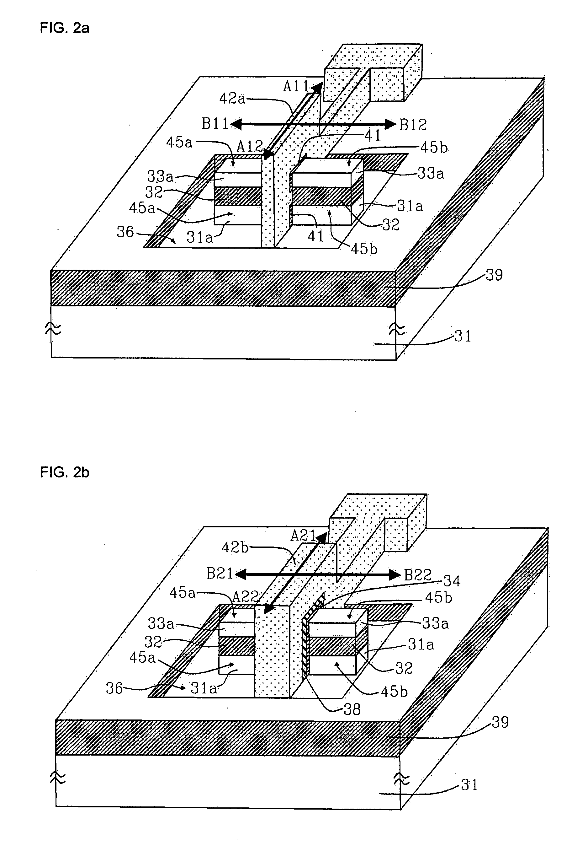
[0025]FIG. 2a is a perspective view illustrating a multi-gate MOS transistor in accordance with a first exemplary embodiment of the present invention. The multi-gate MOS transistor in accordance with the first exemplary embodiment of the present invention is explained below, where references which are not shown will be explained with reference to FIG. 3 to FIG. 11.

[0026] An SOI substrate having a structure that a lower silicon layer 31, a buried oxide layer 32, and an upper silicon layer 33 are sequentially stacked is used. Some thickness of the upper silicon layer 33, the buried oxide layer 32, and the lower silicon layer 31 is etched to form a trench 36 i...


PUM


Abstract

Provided are a multi-gate MOS transistor and a method of manufacturing the same. Two silicon fins are vertically stacked on a silicon on insulator (SOI) substrate, and four side surfaces of an upper silicon fin and three side surfaces of a lower silicon fin are used as a channel. Therefore, a channel width is increased, so that current driving capability of a device is improved, and high performance nano-level semiconductor IC and highly integrated memory IC can be manufactured through the optimization and stability of a process.

Description

CROSS-REFERENCE TO RELATED APPLICATION [0001] This application claims priorities to, and the benefit of Korean Patent Application Nos. 2003-97072 and 2004-69589 filed Dec. 26, 2004 and Sep. 1, 2004, the disclosure of which are hereby incorporated herein by reference in its entirety. BACKGROUND [0002] 1. Field of the Invention [0003] The present invention relates to a multi-gate MOS transistor and a method of manufacturing the same and, more particularly, to a multi-gate MOS transistor having two silicon fins which are perpendicularly stacked and using four side surfaces of an upper silicon fin and three side surfaces of a lower silicon fin as a channel, and a method of manufacturing the same. [0004] 2. Discussion of Related Art [0005] As a semiconductor device is highly integrated, efforts for improving performance such as an operating speed and a driving capability have been made. As a MOSFET has also undergone a continuous size reduction, a problem regarding reliability such as a ...

Claims


Application Information

Patent Timeline
IPC IPC(8): H01L21/336H01L29/423H01L29/78H01L29/786
CPCH01L29/42392H01L29/66795H01L29/785H01L29/78645H01L29/42384
Inventor LEE, DAE WOOROH, TAE MOONKWON, SUNG KUPARK, IL YONGYANG, YIL SUKYU, BYOUNG GONKIM, JONG DAE
Owner ELECTRONICS & TELECOMM RES INST
Learn More