Eureka AIR delivers breakthrough ideas for toughest innovation challenges, trusted by R&D personnel around the world.

Apparatus and method for reduction jet noise from single jets

a jet engine and exhaust flow technology, applied in the direction of machines/engines, vessel construction, marine propulsion, etc., can solve the problems of increasing the noise level of jet aircraft, increasing the exposure of individuals to the noise of commercial and private jet aircraft operation, and undesirable aircraft noise from commercial and private jet aircraft. to achieve the effect of reducing the noise level

Active Publication Date: 2005-10-13
THE BOEING CO
View PDF17 Cites 19 Cited by
  • Summary
  • Abstract
  • Description
  • Claims
  • Application Information

AI Technical Summary

Benefits of technology

[0006] The present invention is directed to an exhaust flow nozzle that reduces the sound pressure level of noise generated by the jet engine, and particularly at areas below the jet engine. The present invention is particularly effective for reducing noise levels produced by a jet engine, as perceived by individuals at ground level, during takeoff and landing operations.
[0011] The various preferred embodiments all modify the jet plume, and the resulting noise, emitted from the exhaust flow nozzle associated with a jet engine such that sound pressure levels at an area below the exhaust nozzle are reduced.

Problems solved by technology

Aircraft noise from commercial and private jet aircraft is an undesirable byproduct of modern aviation.
The growth of air travel and the number of jet aircraft operating at present day airports throughout the world has led to an ever increasing level of jet aircraft noise.
Additionally, as residential dwellings have been constructed closer and closer to commercial airports, more and more individuals have been exposed to noise from the operation of commercial and private jet aircraft.
During takeoff, the engines on commercial jet aircraft are often operated at maximum thrust and therefore generate very significant sound pressure levels.

Method used


Image

  • Apparatus and method for reduction jet noise from single jets
  • Apparatus and method for reduction jet noise from single jets
  • Apparatus and method for reduction jet noise from single jets

Examples


Embodiment Construction

[0039] The following description of the preferred embodiment(s) is merely exemplary in nature and is in no way intended to limit the invention, its application, or uses.

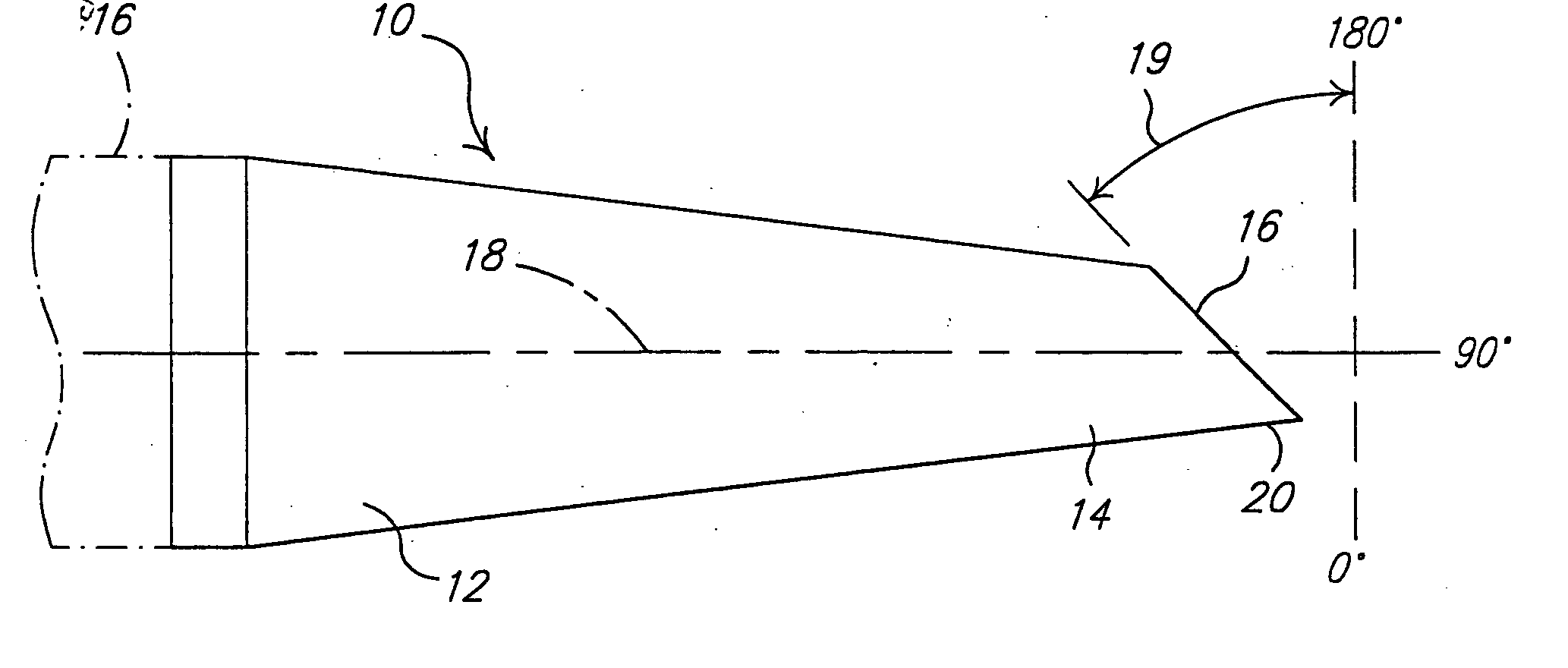
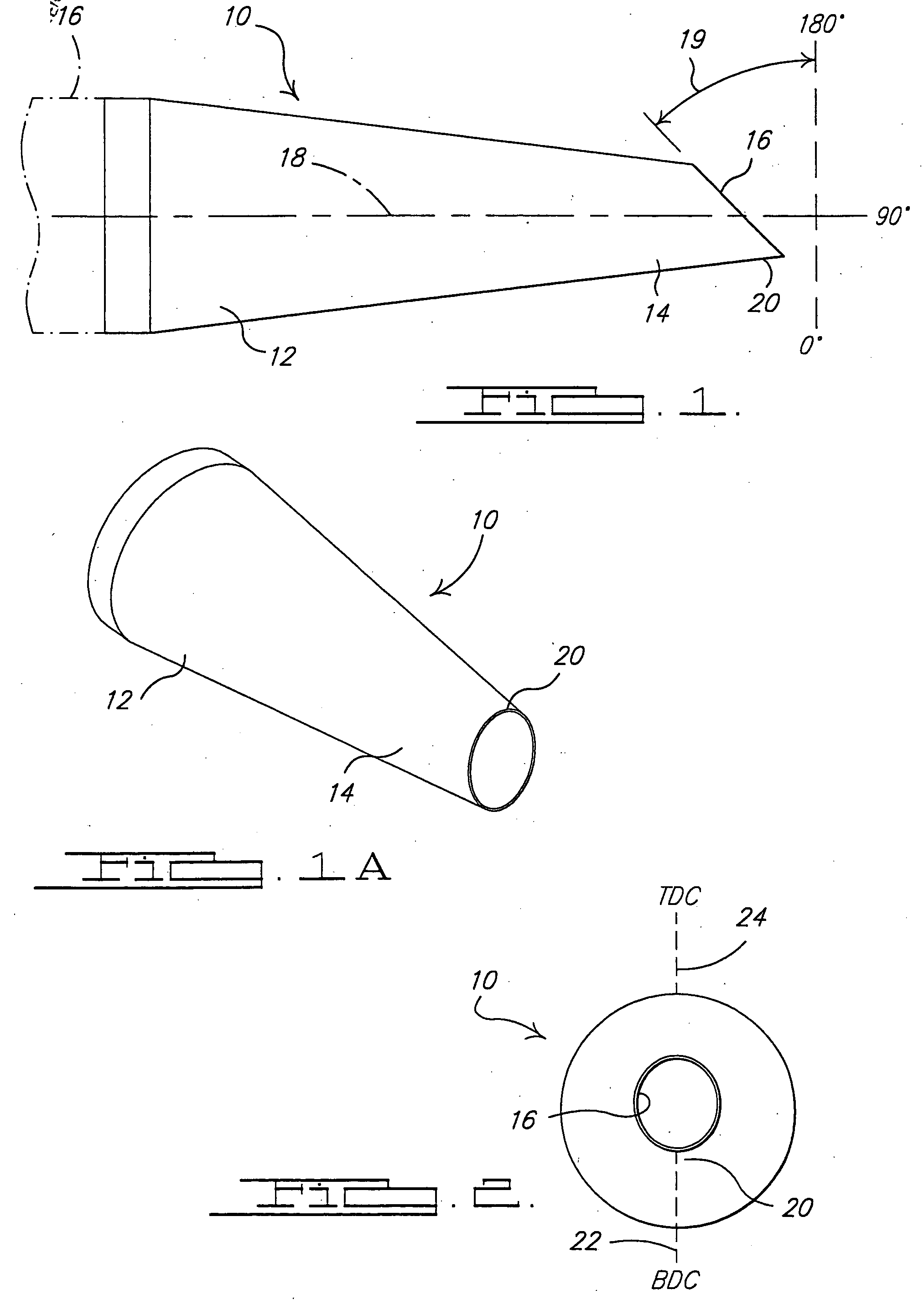
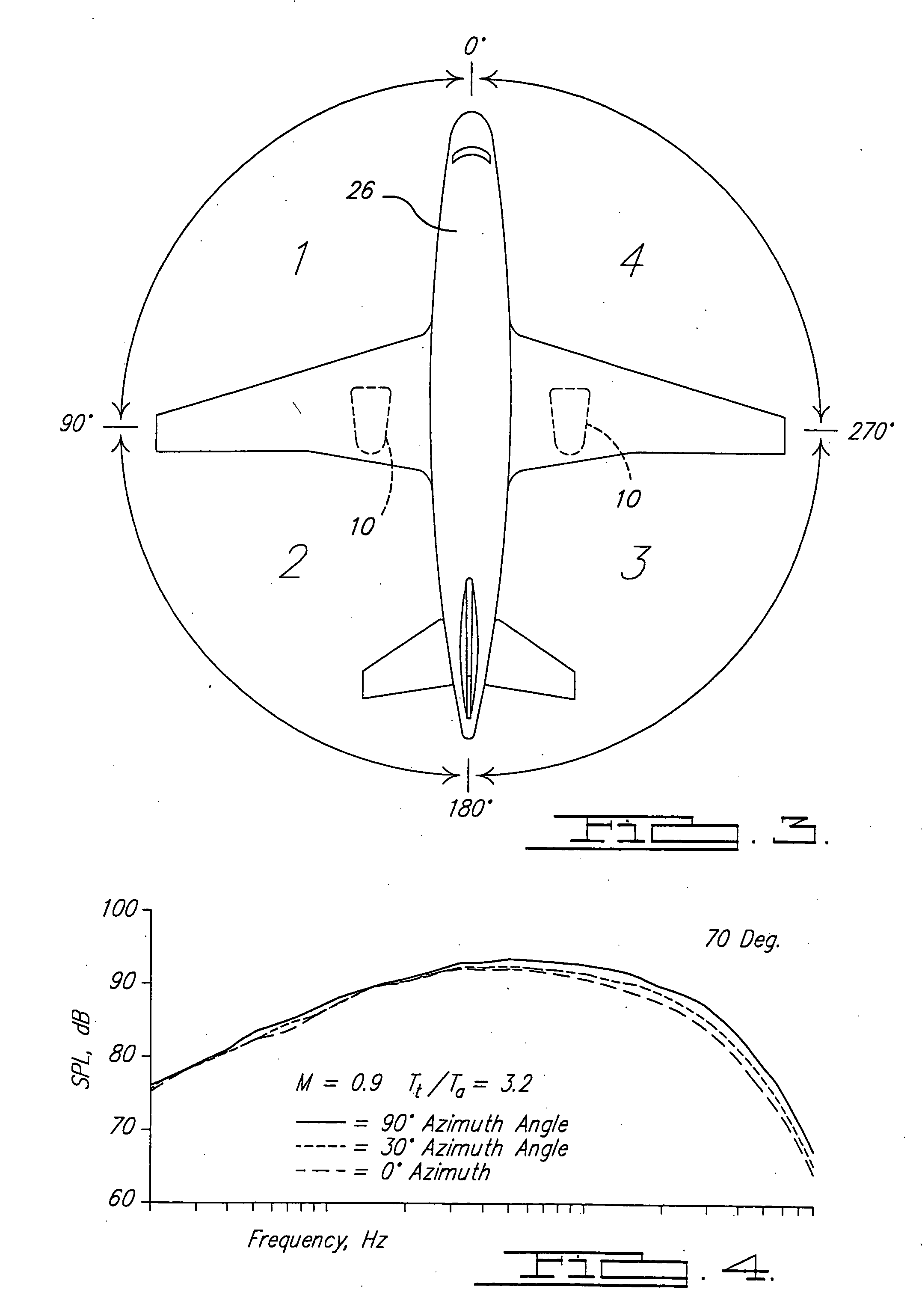
[0040] Referring to FIG. 1, an exhaust flow nozzle 10 is shown in accordance with a preferred embodiment of the present invention. The exhaust flow nozzle forms a tubular component having an upstream end 12 and a downstream end 14. A jet engine 16 generates exhaust gases which are directed into the nozzle 10 and which exit though the downstream end 14. Downstream end 14 includes a beveled edge 16. Beveled edge 16 is beveled at an angle 19 of preferably of about 5°-50°, although it will be appreciated that this angle could vary from this range to meet the needs of a specific aircraft application. The above-mentioned angle is measured relative to a plane orthogonal to the longitudinal center line 18 extending longitudinally though the nozzle 10. In effect, the downstream end 14 forms a “lip” or extension 20 which help...


PUM

PropertyMeasurementUnit
angleaaaaaaaaaa
angleaaaaaaaaaa
polar angleaaaaaaaaaa

Abstract

An exhaust flow nozzle for use with a jet engine. The exhaust flow nozzle includes a beveled downstream edge portion that helps to direct noise generated by the jet engine upwardly away from a ground surface during takeoff and landing operations. One preferred embodiment makes use of a linearly moveable flow altering component that is positioned outside the final flow nozzle. When the flow altering component is in its retracted position it has no effect on the exhaust flow leaving the flow nozzle. Alternative embodiments involve the use of varying edge shapes for the final flow nozzle.

Description

FIELD OF THE INVENTION [0001] This invention relates to exhaust flow nozzles for jet engines and more particularly to an exhaust flow nozzle for a single flow or mixed flow jet engine that reduces noise generated by the jet engine. BACKGROUND OF THE INVENTION [0002] Aircraft noise from commercial and private jet aircraft is an undesirable byproduct of modern aviation. The growth of air travel and the number of jet aircraft operating at present day airports throughout the world has led to an ever increasing level of jet aircraft noise. Additionally, as residential dwellings have been constructed closer and closer to commercial airports, more and more individuals have been exposed to noise from the operation of commercial and private jet aircraft. It will be appreciated that jet aircraft noise is particularly acute during takeoff and landing procedures. During takeoff, the engines on commercial jet aircraft are often operated at maximum thrust and therefore generate very significant s...

Claims


Application Information

Patent Timeline
Patent Type & Authority Applications(United States)
IPC IPC(8): F02K1/38F02K1/48F02K1/00F02K1/44
CPCF02K1/386F02K1/44F02K1/48F05D2250/192Y10T29/49398
Inventor VISWANATHAN, KRISHNAMURTHY
Owner THE BOEING CO
Why Eureka
Eureka Blog
Learn More