Eureka AIR delivers breakthrough ideas for toughest innovation challenges, trusted by R&D personnel around the world.

Method for operating an internal combustion engine

a hybrid drive and internal combustion engine technology, applied in the field of hybrid drive operation, can solve the problems of reducing the performance affecting the reliability of the vehicle drive, and the driver may neither anticipate nor understand the drop in performance, etc., and achieves the effect of simplifying the compression test substantially and ensuring the accuracy of the test results

Active Publication Date: 2012-03-20
AVL LIST GMBH
View PDF18 Cites 6 Cited by
  • Summary
  • Abstract
  • Description
  • Claims
  • Application Information

AI Technical Summary

Benefits of technology

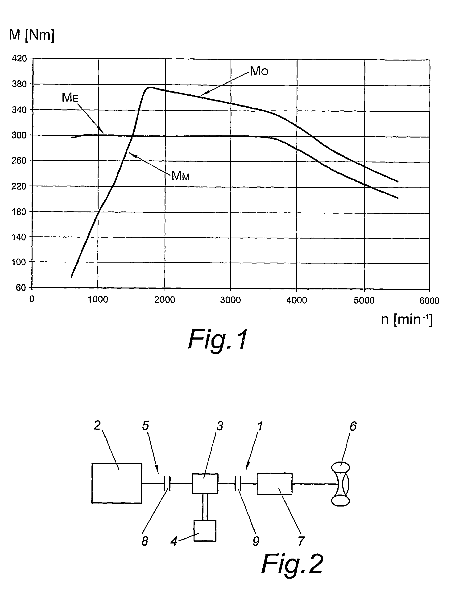
[0018]It is especially advantageous when the internal combustion engine is operated in overload mode when, outside of the proper application area of the electric machine, the full drive power of the internal combustion engine operated in normal load mode is demanded and additionally charge power for loading the energy storage device is to be provided. In this way it is possible to provide sufficient drive torque and recharge the empty energy storage device.
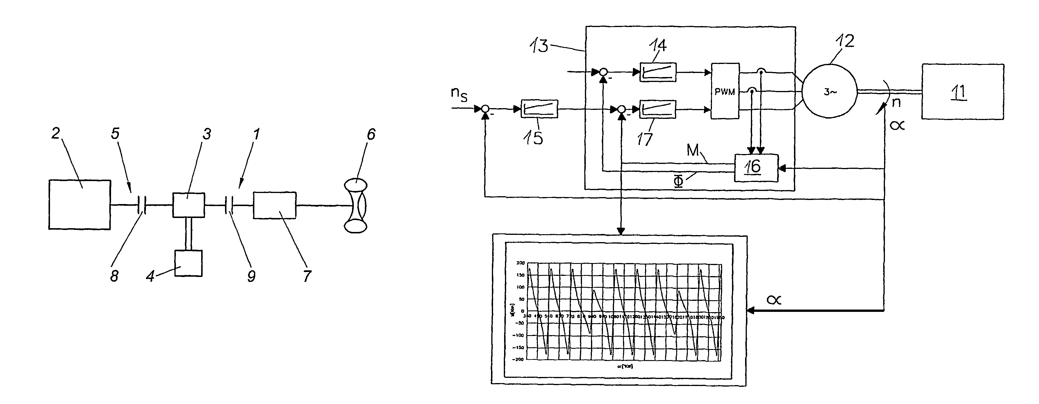
[0038]Due to the fact that the internal combustion engine is operated in partial load or in idle running when charging is required, i.e. when the battery charge state is low, the sound pressure level can thus be reduced considerably. Although the internal combustion engine does not run in the optimal operating range, the comfort of the vehicle and thus the acceptance of the drive concept will thus be improved. The operating strategy can be employed not only at bus stops but also at stops caused by the traffic such as before crossings or the like.

Problems solved by technology

The reproducibility of this function is problematic, especially in the case that the energy storage device is depleted or the electric machine is unable to provide its maximum output, e.g. due to overheating.
In known systems, such situations will lead to drops in performance of the vehicle drive which the driver may neither foresee nor understand.
This is relatively time-consuming because spark plugs or glow plugs need to be removed prior to measurement.
The disadvantageous aspect is that especially during the standstill of the vehicle in the area of the bus stops for example there will be a relatively high noise development by the internal combustion engine.

Method used


Image

  • Method for operating an internal combustion engine
  • Method for operating an internal combustion engine
  • Method for operating an internal combustion engine

Examples


Embodiment Construction

Of The Preferred Embodiment

[0034]A sufficient lubrication of the turbocharger during a cut-off process can be achieved when the oil pump is continued to be operated over a minimum coasting period during a cut-off command preferable following a high-load or full-load phase of the internal combustion engine

[0035]Especially in the case of an oil pump driven by the crankshafts in the internal combustion engine, it is especially advantageous when the internal combustion engine is operated under partial load or idle running for at least a minimum coasting period. When using an electrically drivable oil pump however, it can be provided that the oil pump is operated for at least a minimum coasting period after the cut-off of the internal combustion engine. This ensures a sufficient lubrication of the bearings of the exhaust-gas turbine.

[0036]In order to keep the minimum coasting period as short as possible, it is advantageous when the minimum coasting period is determined depending on at le...


PUM


Abstract

A method for operating a hybrid drive in a vehicle with an internal combustion engine and at least one electric machine connected thereto which is in connection with at least one energy storage device including operating the internal combustion engine is operated in overload mode in at least one preferably exceptional operating situation of the hybrid drive in order to avoid power losses at low loading state of the energy storage device.

Description

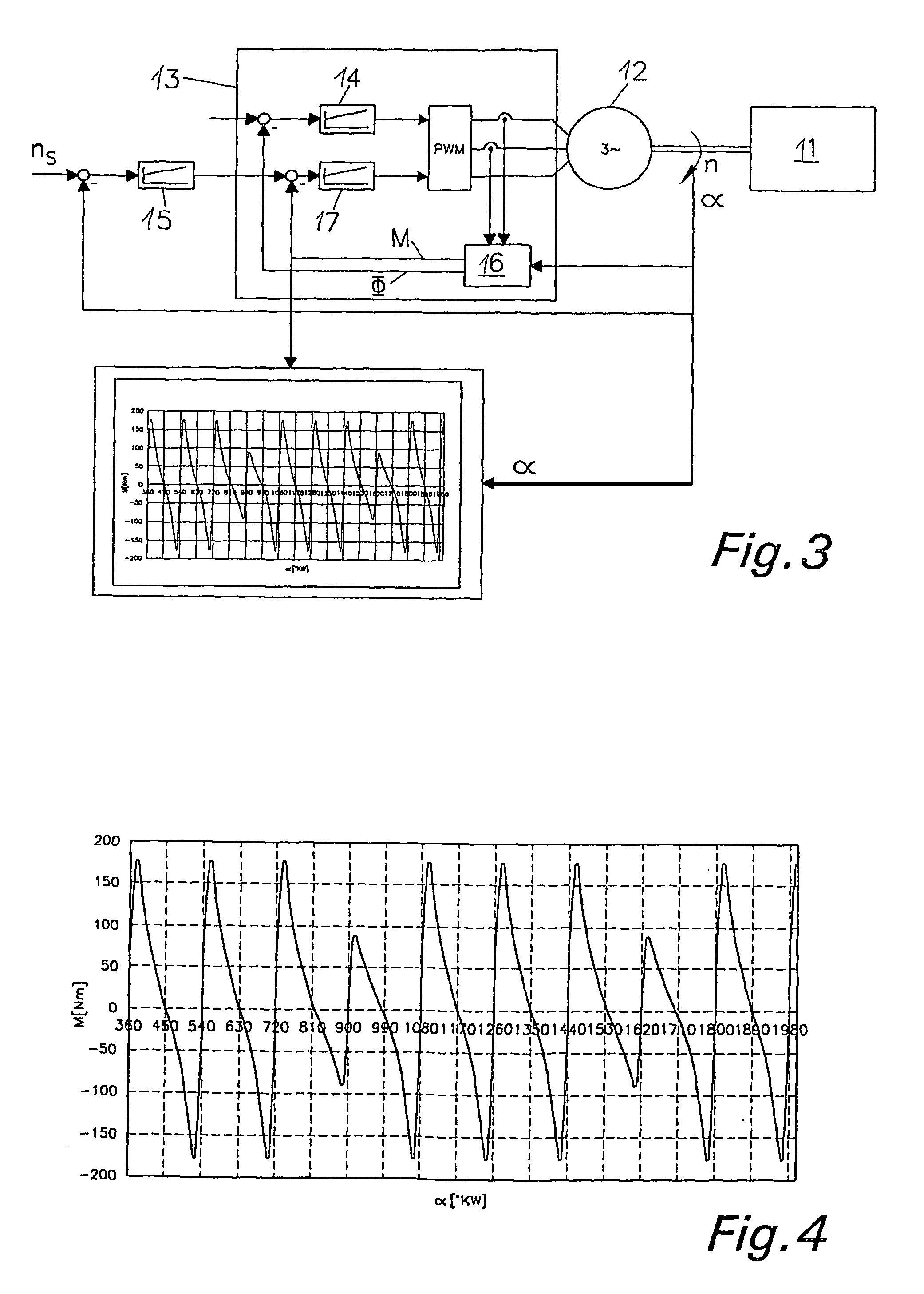
BACKGROUND OF THE INVENTION[0001]1. Field of the Invention[0002]The invention relates to a method for operating a hybrid drive in a vehicle with an internal combustion engine and at least one electric machine connected thereto which is in connection with an energy storage device. The invention further relates to a method for determining differences in compression in a multi-cylinder internal combustion engine which is mechanically rigidly connected with a preferably variable-speed electric induction machine. The invention further relates to a method for operating an internal combustion engine, especially a hybrid vehicle which comprises at least one exhaust turbocharger and at least one oil pump. The invention further relates to a method for operating a vehicle which comprises a serial hybrid drive train with at least one internal combustion engine and at least a first and second electric machine, with the first electric machine being operated in the manner of a generator by the int...

Claims


Application Information

Patent Timeline
IPC IPC(8): B60W10/06B60W10/08B60W10/24B60K6/48B60L50/13B60W10/10B60W30/18F01M1/16
CPCB60K6/46B60K6/28B60L11/123B60W10/02B60W10/06B60W10/10B60W10/115B60W10/26B60W10/30B60W30/18054F02B39/14B60K6/48B60L2210/20B60L2240/28B60L2240/443B60L2240/80B60L2260/12B60L2260/22B60W20/00B60W2510/0623B60W2510/0657B60W2520/10B60W2710/065F01M2001/0215F01M2001/123F01M2011/021Y02T10/6217Y02T10/6221Y02T10/6278Y02T10/7077Y02T10/725Y02T10/7258F16H2059/446B60Y2400/435H02P21/00B60L50/61Y02T10/62Y02T10/64Y02T10/72Y02T10/70B60W20/15B60W30/184Y02T10/7072
Inventor PELS, THOMASKAPUS, PAULEBNER, PETERFISCHER, ROBERTFRAIDL, GUNTERKRIEGLER, WOLFGANGKAUP, CARSTEN
Owner AVL LIST GMBH
Why Eureka
Eureka Blog
Learn More