Hybrid-secondary uncluttered permanent magnet machine and method

Inactive Publication Date: 2005-10-06
UT BATTELLE LLC
View PDF6 Cites 14 Cited by
  • Summary
  • Abstract
  • Description
  • Claims
  • Application Information

AI Technical Summary

Benefits of technology

[0011] This invention provides a multiple-rotor permanent-magnet (PM) machine with a rotor that couples a slip flux to one or more secondary coils through a magnetic coupling uncluttered rotor. Consequently, for the applications such as the hybrid electric vehicles (HEV) that require two individual machines, the size and cost saved by using a single machine is significant. The invention eliminates the main rotor and the auxiliary rotor with windings which were present and electrically connected in the prior art. The stator and slip energy rotor are now magnetically coupled and a slip energy source is provided by peripheral secondary coils in which slip current is induced through the magnetic coupling uncluttered rotor without rotor windings.
[0014] The new approach does not require a rotor winding in either rotor to produce the slip-frequency currents that are subsequently fed to the coil(s) of a peripheral transformer. The function of the new rotors are to directly transform the rotating air-gap flux originated by the PM rotor to the uncluttered flux seen by the stationary secondary coils.

Problems solved by technology

Consequently, for the applications such as the hybrid electric vehicles (HEV) that require two individual machines, the size and cost saved by using a single machine is significant.

Method used


Image

  • Hybrid-secondary uncluttered permanent magnet machine and method
  • Hybrid-secondary uncluttered permanent magnet machine and method
  • Hybrid-secondary uncluttered permanent magnet machine and method

Examples


Embodiment Construction

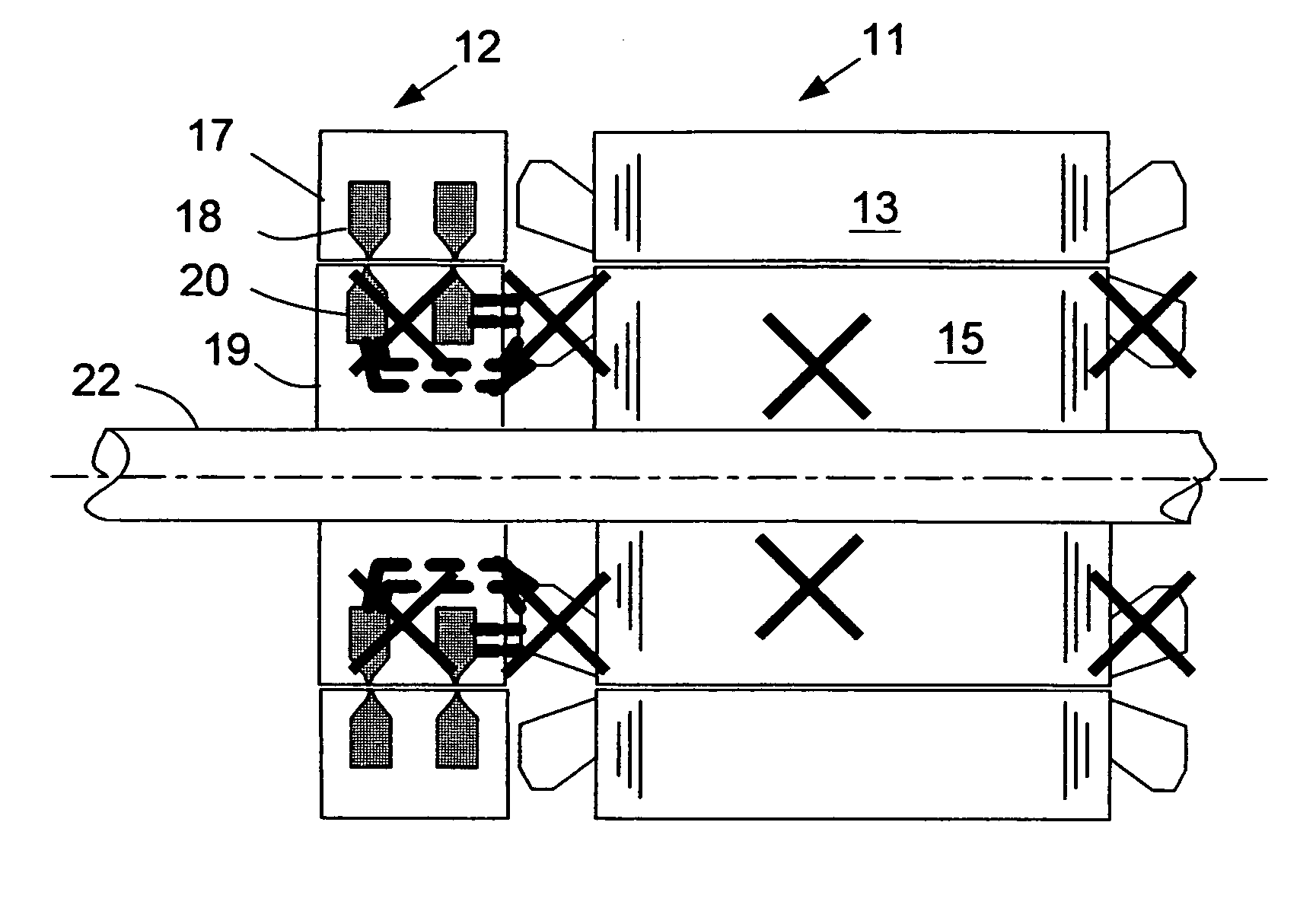
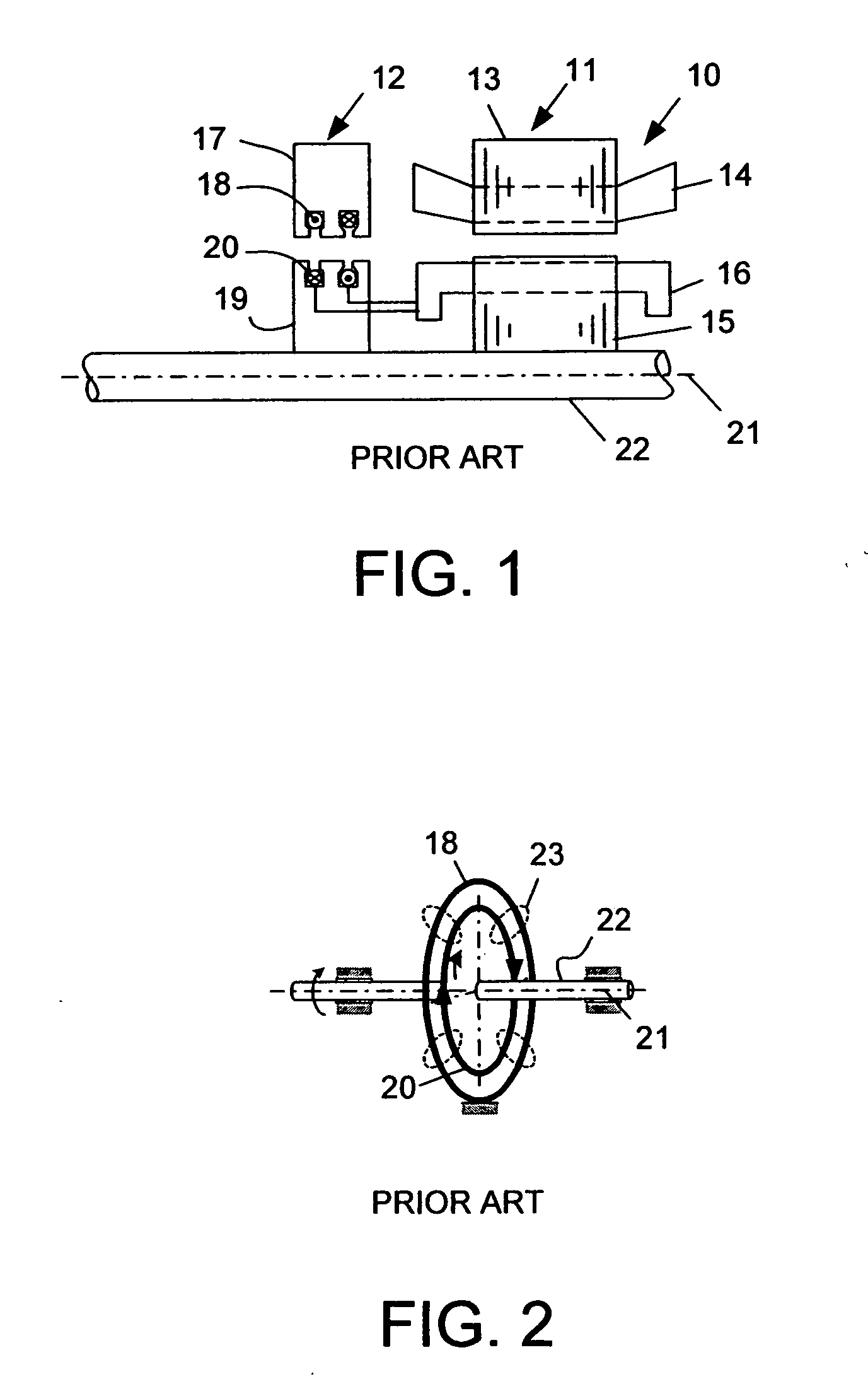
[0033]FIG. 1 illustrates an assembly 10 of an induction motor 11 of the prior art that includes an uncluttered transformer 12 for providing a hybrid secondary. A stator core 13 of the motor 11 is wound with a polyphase winding 14. A rotor core 15 of the motor is wound with a two-phase winding 16. One or more conductors of cast aluminum can also be used on the rotor 15. To the left is a two-phase uncluttered rotating transformer 12. The stator 17 and stator coils 18 of this transformer do not connect to the stator winding 14 of the motor or to the rotor 19 of the transformer 12, but instead are magnetically coupled to the rotor 19 of the transformer 12. The stator 17 and the rotor 19 of the transformer 12 have coils 18, 20 that are peripherally disposed around the axis of rotation 21 for the motor 11 and the transformer 12. The electrical connection of the machine rotor 15 to the transformer rotor 19 allows only the slip energy to be present in the rotor 19 of the transformer 12, and...


PUM

PropertyMeasurementUnit
Speedaaaaaaaaaa
Currentaaaaaaaaaa
Radiusaaaaaaaaaa

Abstract

An electric machine (40) has a stator (43), a permanent magnet rotor (38) with permanent magnets (39) and a magnetic coupling uncluttered rotor (46) for inducing a slip energy current in secondary coils (47). A dc flux can be produced in the uncluttered rotor when the secondary coils are fed with dc currents. The magnetic coupling uncluttered rotor (46) has magnetic brushes (A, B, C, D) which couple flux in through the rotor (46) to the secondary coils (47c, 47d) without inducing a current in the rotor (46) and without coupling a stator rotational energy component to the secondary coils (47c, 47d). The machine can be operated as a motor or a generator in multi-phase or single-phase embodiments and is applicable to the hybrid electric vehicle. A method of providing a slip energy controller is also disclosed.

Description

STATEMENT REGARDING FEDERALLY SPONSORED RESEARCH [0001] This invention was made with Government support under Contract No. DE-AC05-000R22725 awarded to UT-Battelle, LLC, by the U.S. Department of Energy. The Government has certain rights in this invention.TECHNICAL FIELD [0002] The field of the invention is brushless machines, including both ac and dc machines, including both motors and generators, and including induction machines, permanent magnet (PM) machines and switched reluctance machines. DESCRIPTION OF THE BACKGROUND ART [0003] A brushless doubly-fed induction motor (BDFIM) has two sets of stator windings for two p-poles and two q-poles. The rotor winding has a nested cage with 2(p+q) poles. It produces a motor control with a relatively narrow range of speed control. The existing extended rotor cage technology has a drawback in that the both rotational and slip energy are transferred in a cluttered approach to energy transfer. [0004] An induction machine may be viewed as a t...

Claims


Application Information

Patent Timeline
IPC IPC(8): H02K16/00H02K16/02H02K17/42H02K19/06H02K19/10H02K21/24H02K51/00
CPCB60Y2400/607H02K16/00H02K19/06H02K19/103H02K21/24Y10T29/49009H02K57/003H02K57/006Y02T10/641Y10T29/49012H02K51/00H02K99/10H02K99/20Y02T10/64
Inventor HSU, JOHN S.
Owner UT BATTELLE LLC
Why Eureka
Try Eureka