
Restorable vehicle occupant safety system

a vehicle and safety system technology, applied in the direction of pedestrian/occupant safety arrangement, vehicle components, vehicular safety arrangments, etc., can solve the problems of substantially high gas pressure, substantial hot and toxic gas, and injury of vehicle occupants, so as to avoid inflation shock and accelerate the deployment time

Inactive Publication Date: 2005-10-06
CUEVAS JESS +1
View PDF0 Cites 29 Cited by
  • Summary
  • Abstract
  • Description
  • Claims
  • Application Information

AI Technical Summary

Benefits of technology

[0026] Another object of the invention is to slow the rate of airbag inflation by anticipating the collision event and deploy the airbags sooner and slower thus creating a safer environment for the occupant, especially for occupants in an out-of-position condition.
[0028] Another object of the invention is to eliminate the need to fold driver side and passenger side airbags.
[0040] Air from the system will be released and maintained to the knee bolster and side impact stations to a portion of the deployment pressure when the vehicle is started. This feature will enhance a faster deployment time as well as provide an air accumulator function to avoid inflation shock.

Problems solved by technology

These systems require electric ignition and produce substantially high gas pressures.
They also produce substantially hot and toxic gasses that are released into the vehicle thru airbag vents at deployment.
These features can, and have, on occasion, caused injury to vehicle occupants during a collision, particularly when the occupant is out-of position.
The time element between vehicle collision and occupant movement is so fast that these systems must deploy in milliseconds.
This fast time element deployment produces a substantially high noise, especially when several inflators are deployed, such as knee bolsters, side impact modules, rollover inflators and seat belt pretensioners.

Method used


Image

  • Restorable vehicle occupant safety system
  • Restorable vehicle occupant safety system
  • Restorable vehicle occupant safety system

Examples


Embodiment Construction

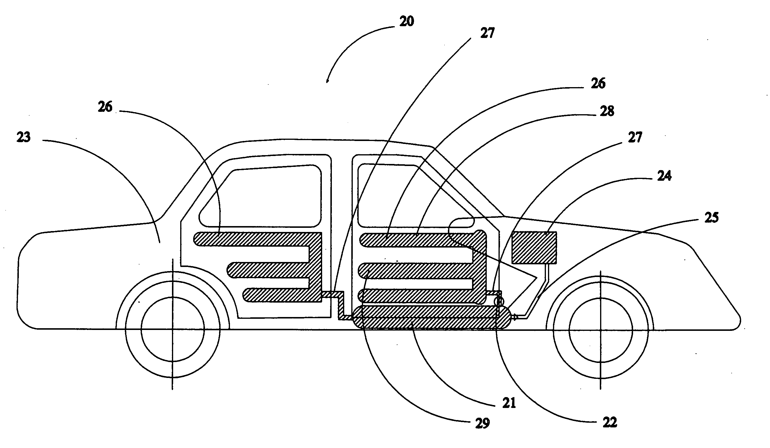
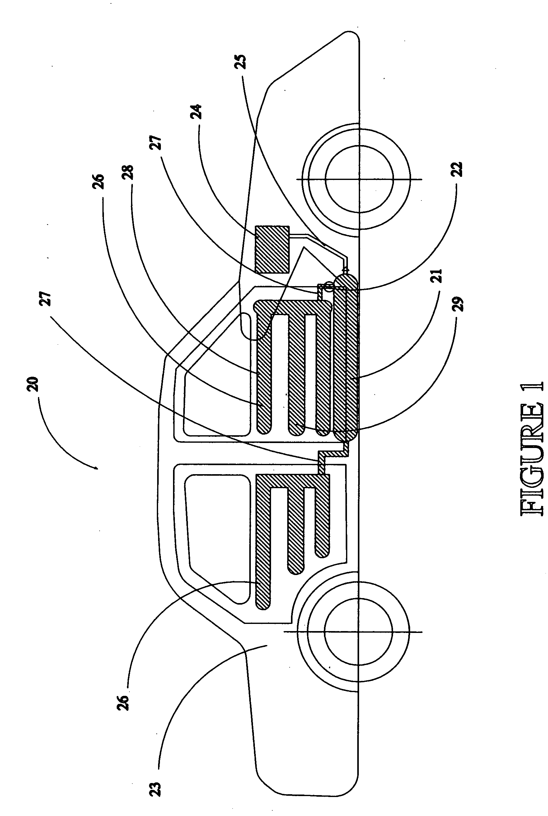
[0052] A restorable vehicle occupant safety system 20 embodying the present invention is illustrated in FIG. 1. A compressed air reservoir 21 is mounted parallel to the driveshaft of vehicle 20 and utilizes an electrically operated deployment valve 22 which is initiated by the vehicle collision detecting sensor system shown in FIG. 10. The reservoir can also be mounted behind the back seat, in the trunk in area 23 or in the instrument panel. The vehicle compressor 24 is fluidly connected to reservoir 21 thru pressure line 25. Air pressure from the reservoir 21 is fluidly connected to the manifold 36 (FIG. 5) and door mounted side impact airbag modules 26 thru convoluted pressure hoses 27. Top airbag channel 28 is separated from channel 29 to provide space for door and window controls.

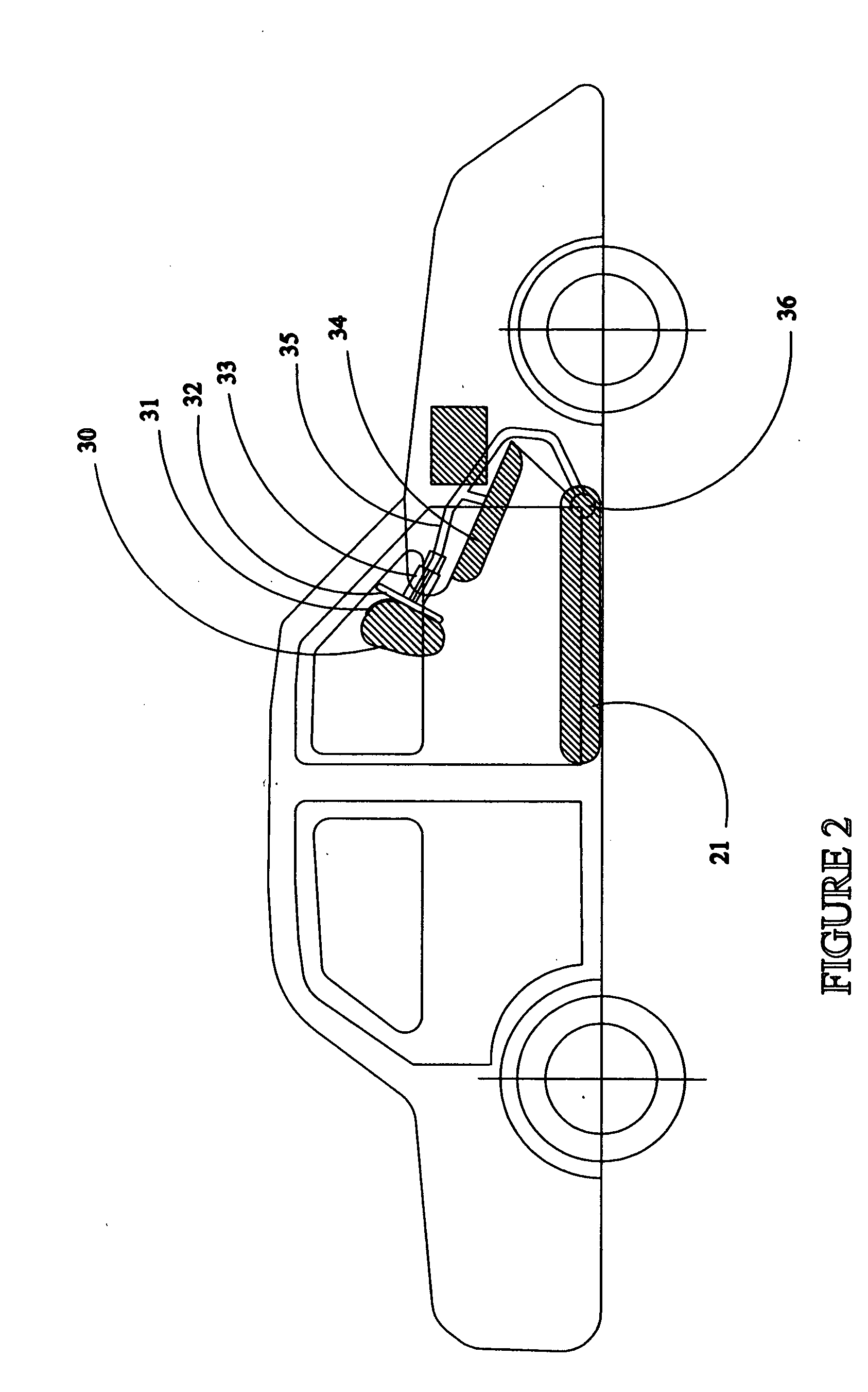
[0053] A view with the driver side face airbag 30 (FIG. 2), is shown in its inflated condition with spring-loaded airbag cover 31 in the open position. Airbag covers will return to their respective ori...


PUM


Abstract

A Restorable Vehicle Occupant Safety System to replace present pyrotechnic airbag systems. The system is comprised of an air pressure storage vessel 21 that is fluidly connected to an air distribution manifold 36, electronic sensors that preclude an impending crash, valves which are sensor activated to inflate airbags for driver, passenger, knee bolster, side impact, and rollover units as well as seatbelt pre-tensioning units. The present system will safely deploy the airbags in a substantially safe increment of time before a crash condition and restore the airbags to their original position in the event the crash condition does not occur.

Description

BACKGROUND OF THE INVENTION [0001] 1. Technical Field [0002] The present invention relates to a restorable non-pyrotechnic vehicle airbag safety system. In particular the present invention relates to an airbag system that deploys at a proper and safe time element before a collision occurs. Sensors on the vehicle will detect an impending collision and cause the deployment of the airbag system through pneumatic valves from a compressed air cylinder which is fed by the vehicle air compressor. If no collision occurs, the airbags will retract to their original restored positions. [0003] 2. Description of the Prior Art [0004] 1. Inflatable vehicle occupant protection devices, such as airbags are known. The airbag is inflated by pyrotechnic fluid provided by an inflator. The airbag typically inflates to a location between the occupant and a vehicle part to protect the occupant from forcefully striking or being struck by the vehicle part. [0005] The airbag and inflator are are commonly moun...

Claims


Application Information

Patent Timeline
Patent Type & Authority Applications(United States)
IPC IPC(8): B60R21/16B60R21/26B60R21/268B60R21/276
CPCB60R21/268B60R21/33B60R21/276
Inventor CUEVAS, JESSKULKARNI, SANJEEV M.
Owner CUEVAS JESS
Learn More