
Accumulator device

a technology of accumulator and accumulator cell, which is applied in the direction of wound/folded electrode electrode, sustainable manufacturing/processing, flat cell grouping, etc., can solve the problems of increasing weight or complicated structure, and achieves the effect of protecting the accumulator cell from external impacts and high versatility and simple structur

Inactive Publication Date: 2005-09-22
SUBARU CORP
View PDF2 Cites 65 Cited by
  • Summary
  • Abstract
  • Description
  • Claims
  • Application Information

AI Technical Summary

Benefits of technology

[0007] The present invention has been made in consideration of the above described disadvantages, and it is an object of the present invention to provide an accumulator device that has a highly versatile and simple structure and can surely protect the accumulator cells from external impacts.
[0019] The accumulator device according to the present invention has a highly versatile and simple structure and can surely protect the accumulator cells from external impacts.

Problems solved by technology

However, on the contrary, when the strength of the package case is thus secured, the structure could be complicated or the weight could be increased.

Method used


Image

  • Accumulator device
  • Accumulator device
  • Accumulator device

Examples


Embodiment Construction

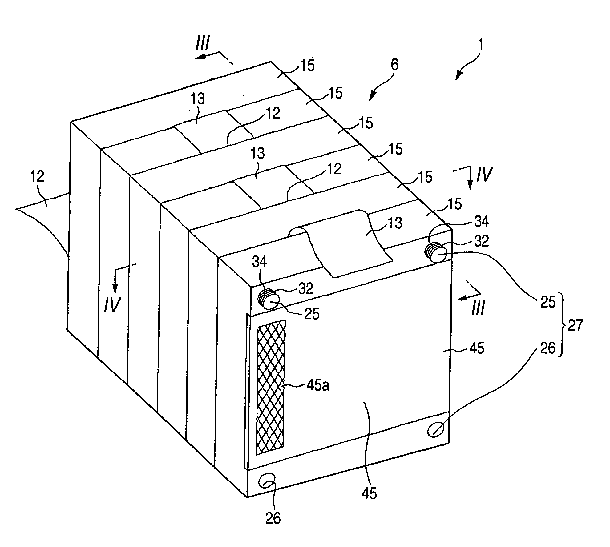
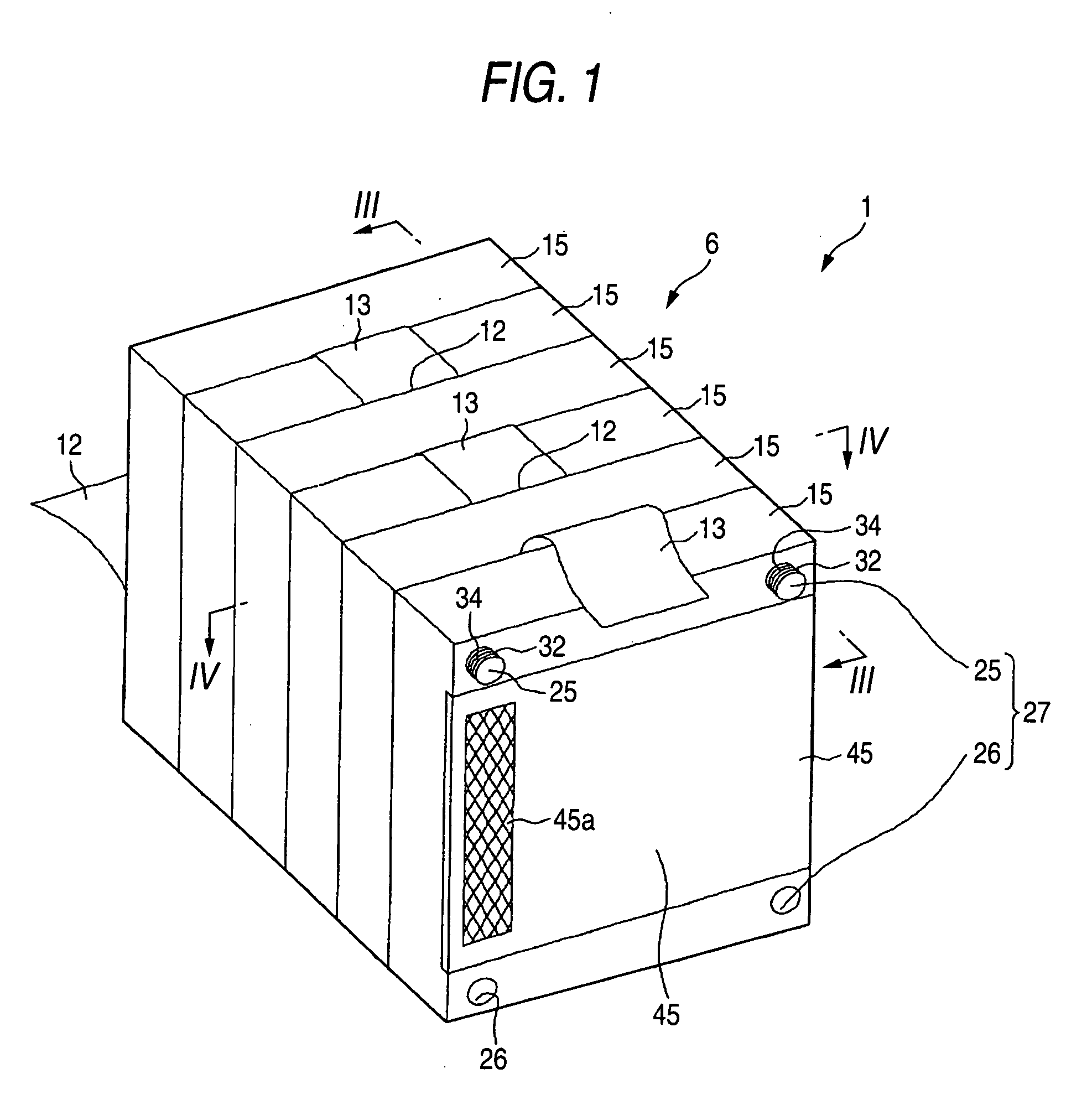
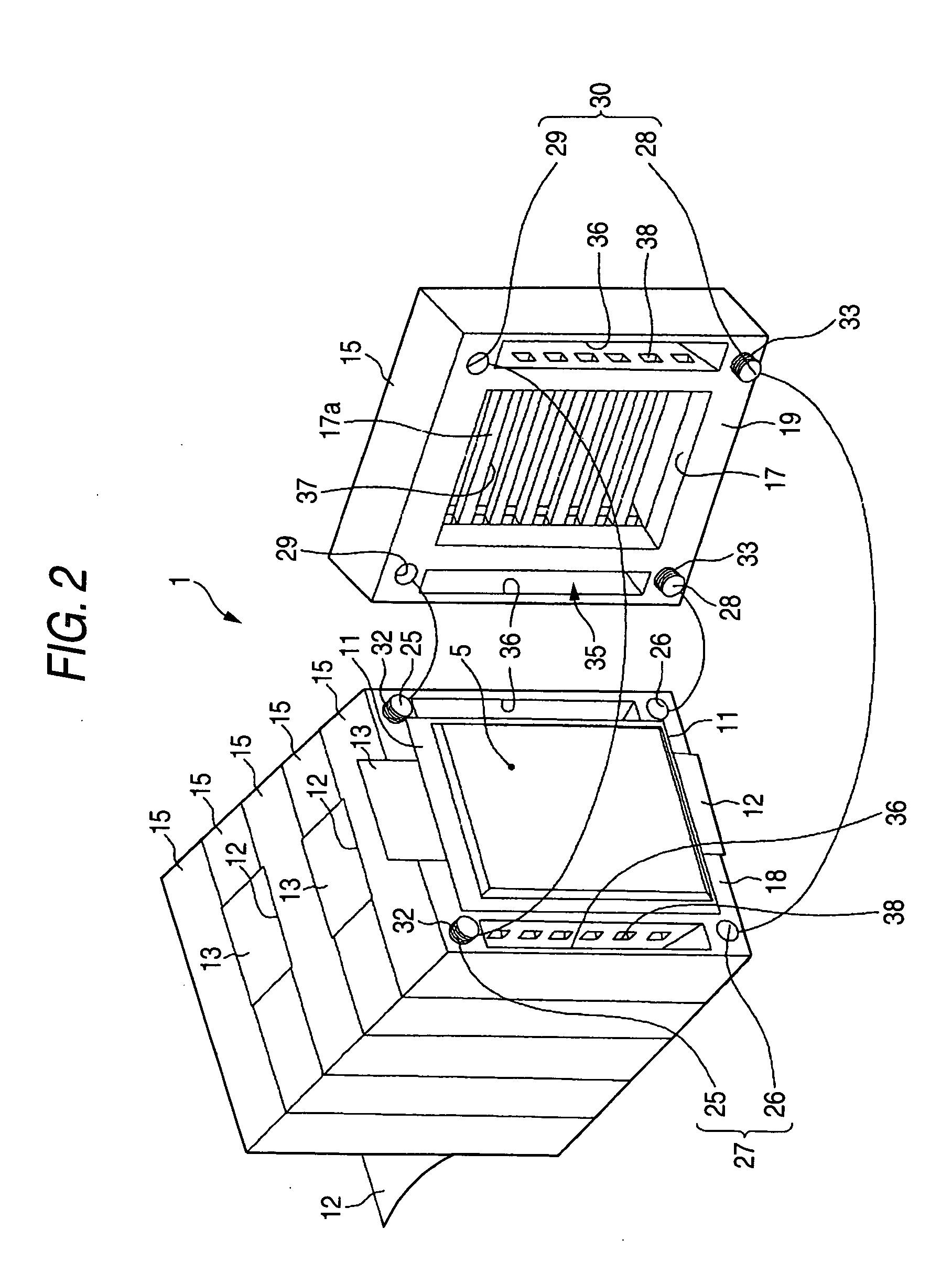
[0034] Hereinafter, preferred embodiments of the present invention will be described with reference to the accompanying drawings. FIGS. 1 to 5 relate to a first embodiment of the invention, and FIG. 1 is a perspective view of an accumulator device, FIG. 2 is a partly exploded, perspective view of the accumulator device in FIG. 1, FIG. 3 is a sectional view taken along line III-III in FIG. 1, FIG. 4 is a sectional view taken along line IV-IV in FIG. 1, and FIG. 5 is a perspective view of series-connected flat laminate cells.

[0035] In FIGS. 1 to 4, the reference numeral 1 represents an accumulator device mounted for example in an electric vehicle (EV), a hybrid electric vehicle (HEV), or a fuel cell vehicle (FCV), and the accumulator device 1 includes a plurality of (five in the shown example) flat laminate cells 5 as the accumulator cells, and a package case 6 that accommodates the flat laminate cells 5.

[0036] Note that a flat laminate cells 5 in a substantially rectangular shape i...


PUM

PropertyMeasurementUnit
elasticaaaaaaaaaa
electrically conductingaaaaaaaaaa
heat-shrinkableaaaaaaaaaa

Abstract

A package case is structured by a plurality of substantially identical and flat frames stacked on one another. Flat laminate cells (accumulator cells) are individually accommodated in the frames and stacked on one another, so that the number of flat laminate cells (accumulator cells) can readily be changed simply by increasing / decreasing the number of frames to be stacked to meet energy needs and the like. The accumulator device is segmented using the plurality of flat frames, so that externally applied impacts can readily be dispersed and the impact transmitted to the flat laminate cells (accumulator cells) can be reduced without reinforcing the accumulator device 1 with more than necessary strength.

Description

[0001] This application claims foreign priority based on Japanese patent application No. JP-2004-077638, filed on Mar. 18, 2004, the contents of which is incorporated herein by reference. BACKGROUND OF THE INVENTION [0002] The present invention relates to an accumulator device including a plurality of connected accumulator cells such as a rechargeable battery, a capacitor, and a generator module. [0003] As an accumulator device for a vehicle such as an electric vehicle (EV), a hybrid electric vehicle (HEV), and a fuel-cell vehicle (FCV), a battery pack which is relatively easy to handle and structured by connecting a plurality of small sized accumulator cells (such as a rechargeable battery, a capacitor, and a generator module) is extensively used. [0004] A main part of the accumulator device (battery pack) of this kind is generally structured by integrally accommodating a predetermined number of accumulator cells (element cells) set depending on voltage and capacity specifications ...

Claims


Application Information

Patent Timeline
Patent Type & Authority Applications(United States)
IPC IPC(8): H01G9/00H01G2/08H01G9/26H01G11/10H01G11/12H01G11/18H01G11/74H01G11/78H01M10/04H01M10/60H01M10/613H01M10/625H01M10/647H01M10/6557H01M10/6563H01M10/6566H01M10/6568H01M50/211H01M50/264
CPCH01M2/0245H01M10/5004H01M10/0431H01M2/1077H01M10/613Y02E60/10H01M50/258Y02P70/50H01M50/264H01M50/211H01M50/20H01M50/30
Inventor SAKURAI
Owner SUBARU CORP
Learn More