
Optical image measuring apparatus

a measuring apparatus and optical image technology, applied in the field of optical image measuring apparatus, can solve the problems of difficult shortening the measurement time in view of measurement fundamentals, difficult to actually use the apparatus in fields that require high-resolution images, and reducing the accuracy of the measurement, so as to achieve the effect of effectively obtaining the direct current component and simplifying the structure of the apparatus

Inactive Publication Date: 2005-09-22
KK TOPCON
View PDF1 Cites 15 Cited by
  • Summary
  • Abstract
  • Description
  • Claims
  • Application Information

AI Technical Summary

Benefits of technology

[0023] The present invention has been made in view of the above-mentioned circumstances. An object of the present invention is to provide an optical image measuring apparatus capable of effectively obtaining a direct current component of a heterodyne signal composed of background light of interference light.
[0024] Another object of the present invention is to provide an optical image measuring apparatus in which usefulness is improved by an increase in degree of freedom of a sampling mode for interference light.

Problems solved by technology

Therefore, the measurement of the object to be measured 105 can be time consuming.
In addition, it is hard to shorten a measurement time in view of measurement fundamentals.
Therefore, it is likely to be hard to actually use the apparatus in fields that require a high-resolution image, such as a medical field and an industrial field.
However, other obtaining methods are not specifically disclosed, so the degree of freedom of a measurement mode is small.
However, it is hard to realize this by the optical image measuring apparatus described in those patent documents.

Method used


Image

  • Optical image measuring apparatus
  • Optical image measuring apparatus
  • Optical image measuring apparatus

Examples


first modified example

(First Modified Example of Mode for Obtaining Direct Current Component)

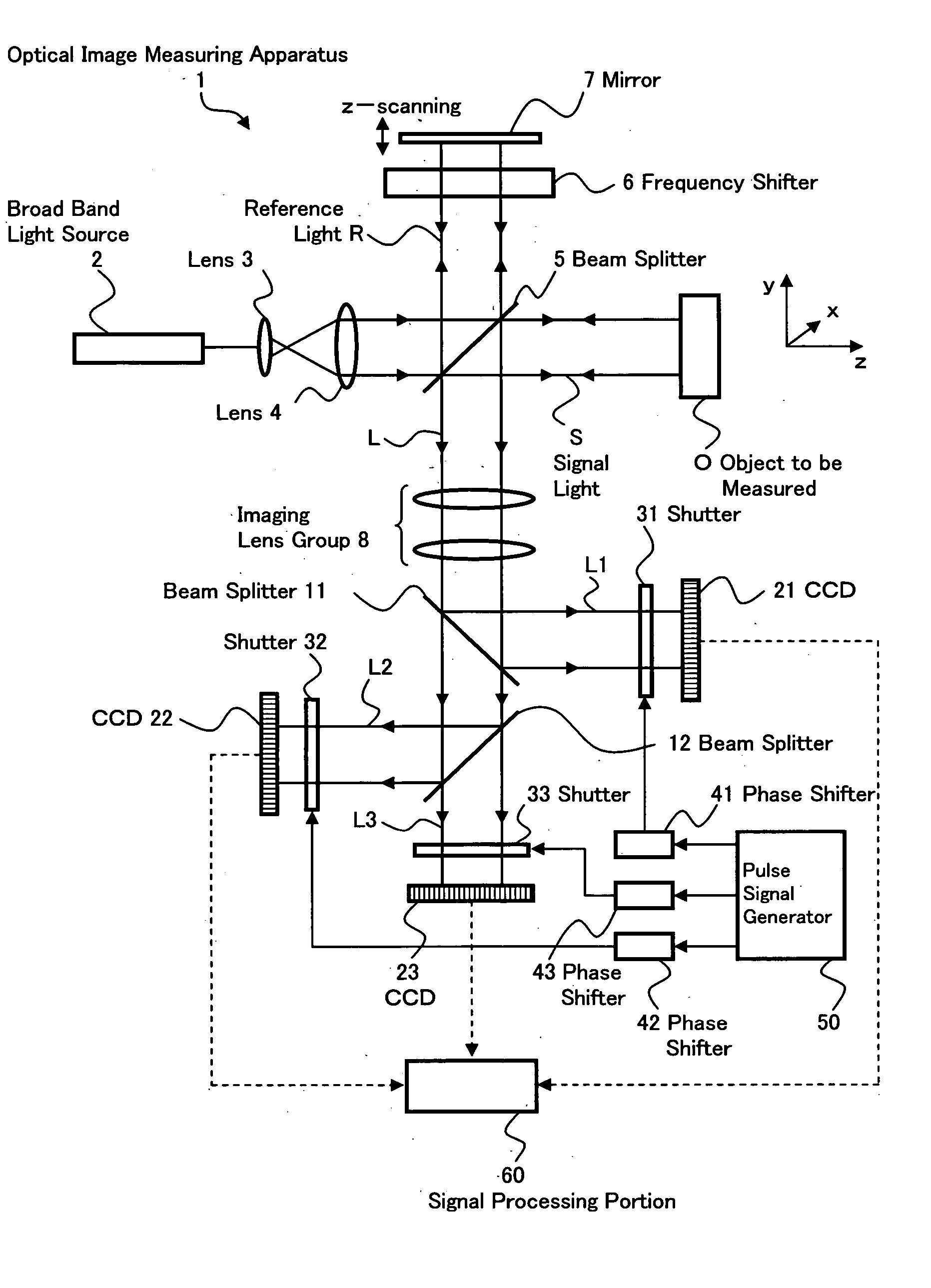
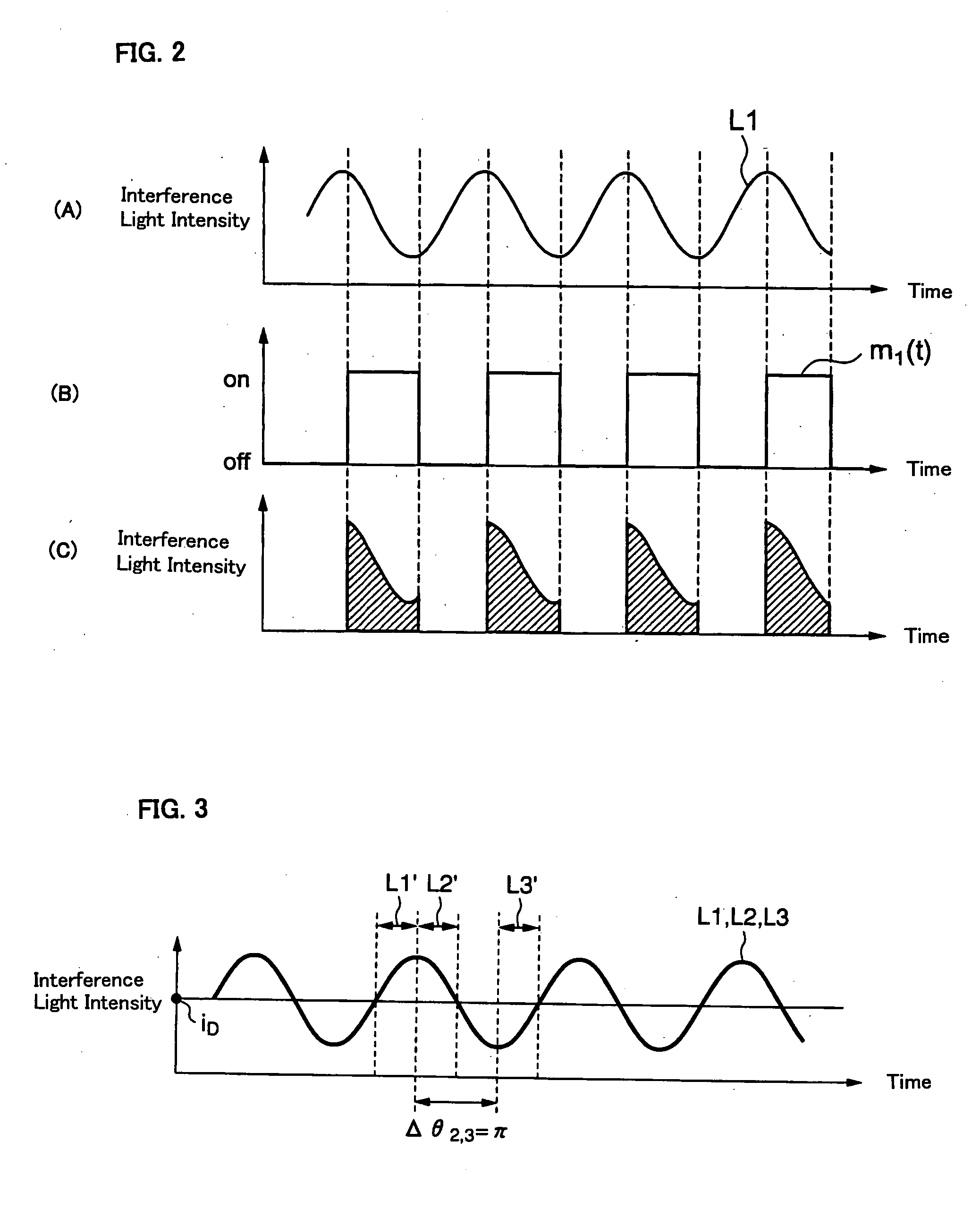
[0105] First, a method of calculating the direct current component based on the electrical signals outputted from the two CCDs as in the above-mentioned embodiment will be described with reference to FIG. 3. Here, a structure including the CCDs 22 and 23 shown in FIG. 1 is used. However, even in an optical image measuring apparatus including only two CCDs and an optical image measuring apparatus including four or more CCDs, the same calculation processing can be performed.

[0106] Therefor, the phase difference Δθ2,3 between the sampling function m2(t) and the sampling function m3(t) is set to π (180 degrees) For example, as shown in FIG. 3, a sampling range L1′ of the interference light beam L1 sampled based on the sampling function m1(t) is set to 0 to π / 4. A sampling range L2′ of the interference light beam L2 sampled based on the sampling function m2(t) is set to π / 4 to π / 2. A sampling range L3′ of the interfe...

second modified example

(Second Modified Example of Mode for obtaining Direct Current Component)

[0111] Next, a method of calculating the direct current component based on an electrical signal outputted from a single CCD will be described. FIG. 4 shows a sampling mode for this method. Here, a structure including the CCD 22 of the optical image measuring apparatus 1 shown in FIG. 1 is used. However, even in an optical image measuring apparatus including only a single CCD and an optical image measuring apparatus including an arbitrary number of CCDs, the direct current component can be similarly obtained.

[0112] In this modified example, measurement is performed plural times using the CCD 22. The direct current component is calculated based on electrical signals from the CCDs 22 during the plural-time measurement. Therefore, sampling of an interference light beam L2 is performed plural times (for example, twice) such that a phase difference Δθ2,2 becomes π. For example, two sampling functions for sampling the...

third modified example

(Third Modified Example of Mode for Obtaining Direct Current Component)

[0116] A third modified example of a mode for obtaining the direct current component composed of the background light will be described. In this modified example, only a single CCD (for example, the CCD 22) is used as in the second modified example. Therefore, a frequency of the sampling function m2(t) is set to a value which is not synchronized with the frequency of the heterodyne signal (beat frequency) fif. According to such setting, parts of the interference light beam which have different phases are successively sampled, with the result that (substantially) the entire phase range 0 to 2π of the interference light beam is sampled. Thus, when sampling results are time-averaged, the alternating current component is canceled to extract only the direct current component.

[0117] An example of this modified example will be described with reference to FIG. 5. Assume that a period T0 of the heterodyne signal is expre...


PUM

PropertyMeasurementUnit
coherent lengthaaaaaaaaaa
optical image measuringaaaaaaaaaa

Abstract

An optical image measuring apparatus capable of effectively obtaining a direct current component of a heterodyne signal which is composed of background light of interference light is provided. The optical image measuring apparatus includes: an optical interference system in which a light beam from a light source is divided into signal light and reference light by a beam splitter, a frequency of the reference light is shifted by a frequency shifter, and the signal light propagating through an object to be measured and the reference light reflected on a mirror are superimposed on each other by the beam splitter to produce interference light; beam splitters for dividing the interference light into interference light beams; shutters serving as an intensity modulating unit for modulating intensities of the respective interference light beams at predetermined intervals; CCDs for receiving the respective interference light beams whose intensities are modulated and outputting electrical signals; and a signal processing portion serving as a calculating unit for calculating an intensity of the direct current component corresponding to the background light of the interference light based on the outputted electrical signals.

Description

BACKGROUND OF THE INVENTION [0001] 1. Field of the Invention [0002] The present invention relates to an optical image measuring apparatus employing a structure in which an object to be measured which is particularly a light scattering medium is irradiated with a light beam and a surface form or inner form of the object to be measured is measured based on a reflected light beam or a transmitted light beam to produce an image of a measured form. More particularly, the present invention relates to an optical image measuring apparatus for measuring the surface form or inner form of the object to be measured by using an optical heterodyne detection method to produce the image of the measured form. [0003] 2. Description of the Related Art [0004] In recent years, attention has been given to optical imaging techniques for producing an image of a surface or inner portion of an object to be measured using a laser light source or the like. In contrast to the conventional X-ray CT technique, op...

Claims


Application Information

Patent Timeline
Patent Type & Authority Applications(United States)
IPC IPC(8): A61B10/00G01B9/02G01B11/24G01J9/02G01J9/04G01N21/17
CPCG01J2009/0234G01B9/02007G01B2290/45G01B9/02041G01B9/02069G01B9/02003
Inventor CHAN, KINPUIAKIBA, MASAHIROFUKUMA, YASUFUMIOTSUKA, HIROYUKITSUKADA, HISASHI
Owner KK TOPCON
Learn More