
Prosthetic cardiac valves and systems and methods for implanting thereof

a technology applied in the field of prosthetic cardiac valves and systems, can solve the problems of increasing the workload on the heart, debilitating symptoms, and excessive backward flow of blood through the valve into the prior chamber, and achieves the effects of facilitating the anchoring of the valve mechanism, facilitating the delivery and deployment of the fixation mechanism, and simplifying the procedure of cardiac valve replacemen

Active Publication Date: 2005-09-15
MEDTRONIC INC
View PDF99 Cites 478 Cited by
  • Summary
  • Abstract
  • Description
  • Claims
  • Application Information

AI Technical Summary

Benefits of technology

[0026] Some of the embodiments are suitable for either surgical, minimally invasive or endovascular delivery approaches. At least a portion of the valve mechanism and / or fixation mechanism is flexible so as to be compressible or collapsible or foldable to provide a low-profile state for minimally invasive and endovascular delivery, and which is expandable for deployment at an implant site. In certain variations of these, the valve mechanism is held together in the collapsed or folded condition by magnetic means which means may also facilitate anchoring of the valve mechanism when deployed at the implant site. Still other variations provide a stent mechanism to facilitate delivery and deployment of the fixation mechanism.
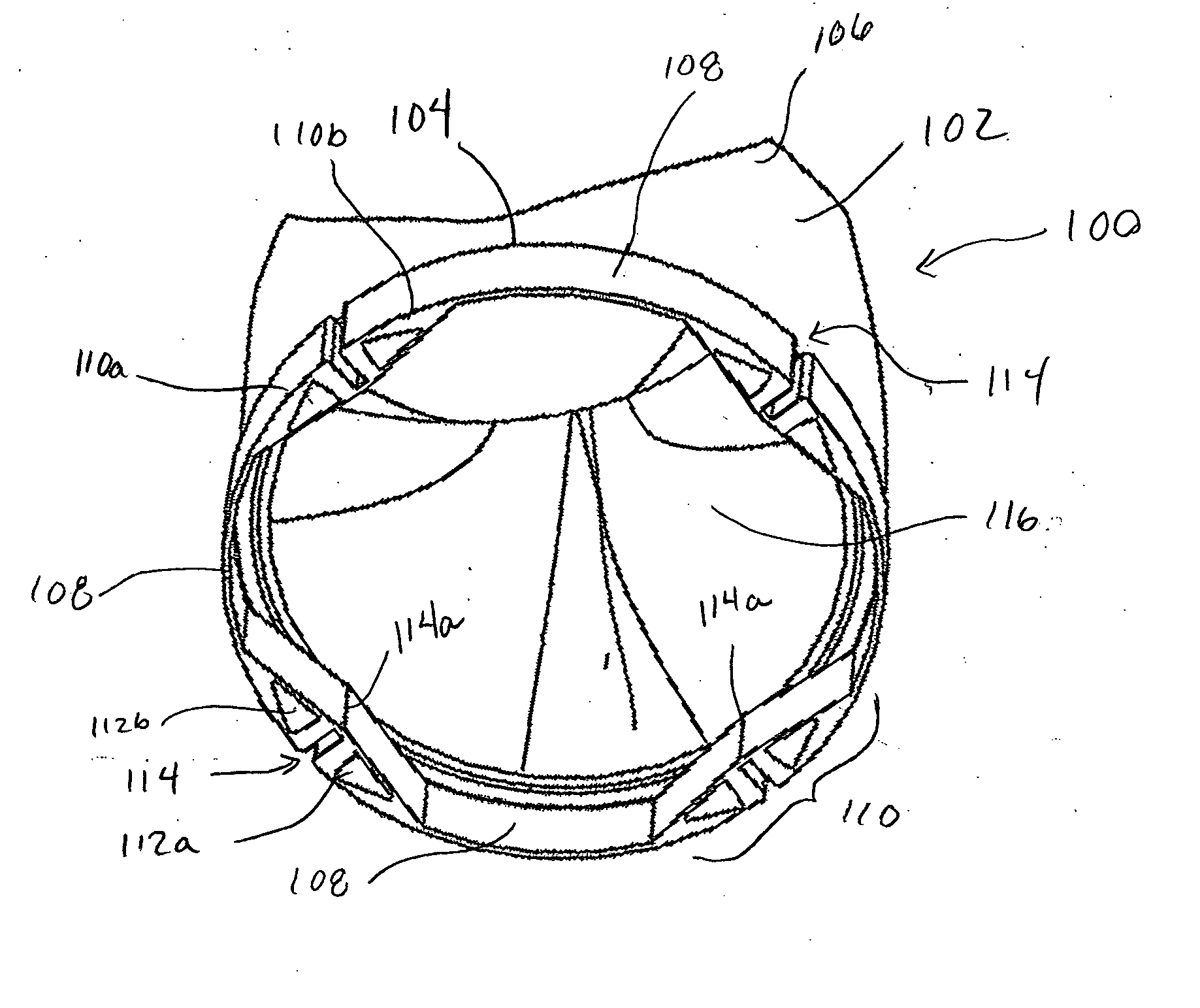
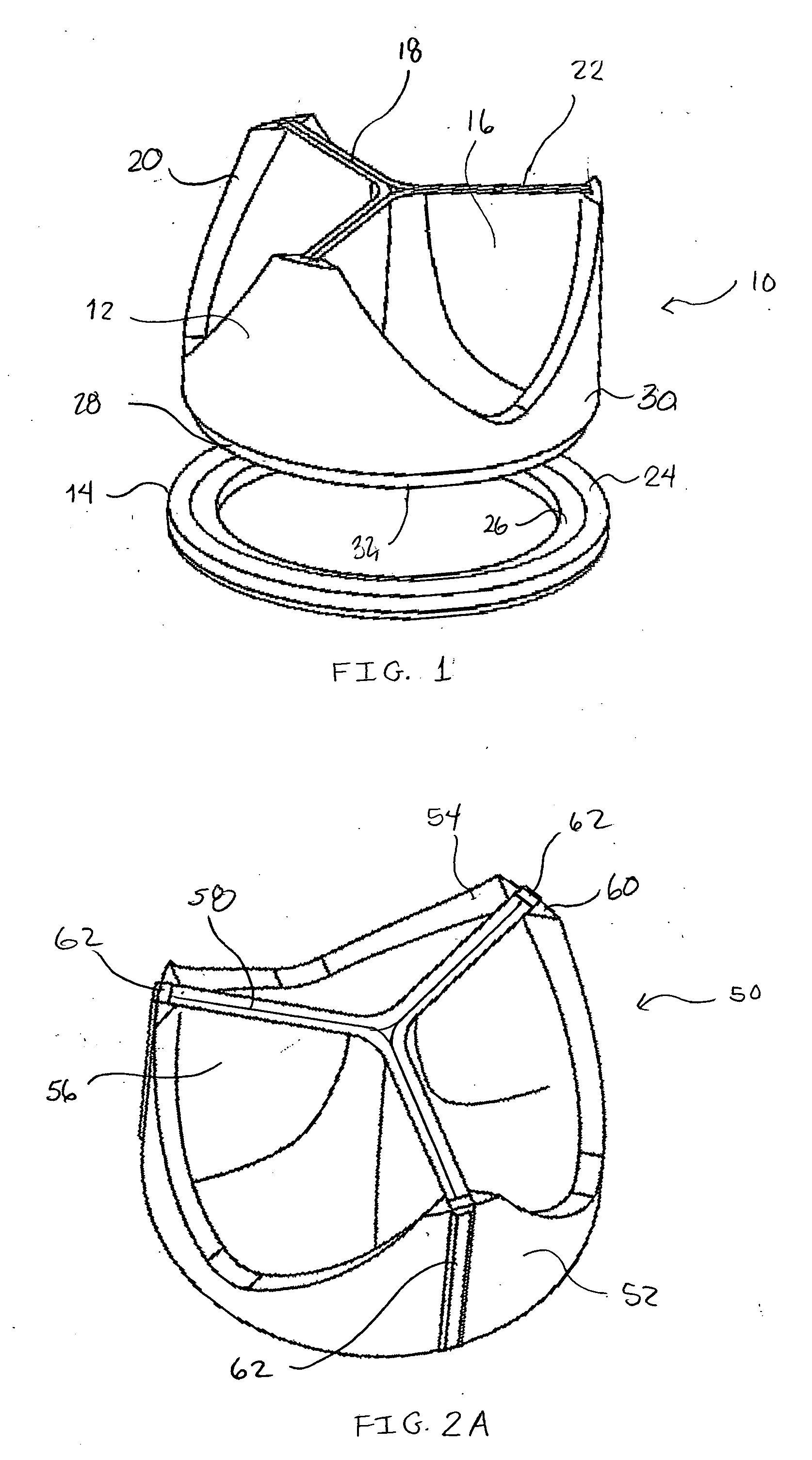
[0039] A feature of the present invention is a valve implantation system in which the valve and fixation mechanism (mounting or docking ring) are separable structures that may be readily engaged and disengaged.

Problems solved by technology

Diseased heart valves may be categorized as either stenotic, wherein the valve does not open sufficiently to allow adequate forward flow of blood through the valve, or incompetent or insufficient, wherein the valve does not close completely, causing excessive backward flow of blood through the valve into the prior chamber when the valve is closed.
Both of these conditions increase the workload on the heart and, if left untreated, can lead to debilitating symptoms including congestive heart failure, permanent heart damage and ultimately death.
Dysfunction of the left-sided valves—the aortic and mitral valves—is typically more serious since the left ventricle is the primary pumping chamber of the heart.
Many dysfunctional valves, however, are diseased beyond the point of repair.
In addition, valve repair is usually more technically demanding and only a minority of heart surgeons is capable of performing complex valve repairs.
The aortic valve, and less frequently the pulmonary valve, are more prone to stenosis, which typically involves the buildup of calcified material on the valve leaflets, causing them to thicken and impairing their ability to fully open to permit adequate forward blood flow.
Most diseased aortic and pulmonic valves are replaced rather than repaired because their function can be easily simulated with a replacement prosthesis and because the typical types of damage to these valves is not easily repairable.
While regurgitant mitral valves can be repaired, many are replaced due to the complexities of surgically correcting the underlying redundant valve segments, ruptured chordae, and papillary muscle malposition.
If such blood clots form on the valve, they may preclude the valve from opening or closing correctly or, more importantly, the blood clots may disengage from the valve and embolize to the brain, causing a stroke.
The anticoagulant drugs that are necessary to prevent this are expensive and potentially dangerous in that they may cause abnormal bleeding or other side effects.
Mechanical valves have the further disadvantage in that the mounting cuffs or sewing rings occupy space, narrowing the effective orifice area of the valve and reducing cardiac output.
The major disadvantage of tissue valves is that they lack the long-term durability of mechanical valves.
Tissue valves have a significant failure rate, usually appearing at approximately 8 years following implantation, although preliminary results with the new commercial pericardial valves suggest that they may last longer.
One cause of these failures is believed to be the chemical treatment of the animal tissue that prevents it from being antigenic to the patient.
While the stented tissue valves guarantee alignment of the commissures, they cause very high stresses on the commissures when the valve cusps move between open and closed positions.
Additionally, the frames or stents can take up valuable space inside the aorta such that there is a narrowing at the site of valve implantation.
As with mechanical valves, the frame includes artificial materials which can increase the risk of new infection or perpetuate an existing infection.
Despite the known advantages of using biologic prosthetic heart valves without artificial supporting devices such as permanent stents or frames, relatively few surgeons employ this surgical technique due to its high level of difficulty.
When unsupported or unstented by a frame or stent, biologic replacement heart valves are flimsy and overly flexible such that the commissures of the heart valve do not support themselves in the proper orientation for implantation.
For these reasons, it is very difficult to secure the commissures properly into place.
Suturing of a valve is a very complex procedure, requiring the utmost care and accuracy.
Repetition of the suturing process causes excessive perforation of the native valve annulus subjecting it to risk of tearing and may effect the functioning of the replacement valve once permanently placed.
This risk also presents itself in subsequent surgeries performed to replace a prosthetic valve suffering from excessive wear or mechanical failure.
After a number of replacements, the tissue surrounding the valve becomes perforated and scarred making attachment of each new replacement valve progressively more difficult for the surgeon and riskier for the patient.
In addition to the complexity of valve suturing, conventional heart valve replacement surgery can be very invasive, involving access to the patient's heart through a large incision in the chest, such as a median stemotomy or a thoracotomy.
Although most patients tolerate limited periods of cardiopulmonary bypass and cardiac arrest, these maneuvers are known to adversely affect all organ systems.
If severe, these complications can lead to permanent disability or death.
The risk of these complications is directly related to the amount of time the patient is on the heart-lung machine (“pump time”) and the amount of time the heart is stopped (“cross-clamp time”).
The complex suturing of the prosthetic valve within the valve annulus and the subsequent knot tying involved in valve replacement procedures, as discussed above, is very time consuming, requiring a significant amount of pump time.
However, the time involved in these minimally invasive procedures is often greater than with conventional valve replacement procedures as the suturing process must now be performed with limited access to the valve and, thus, limited dexterity even in the hands of experienced surgeons.
An improperly placed staple or fastener can be very difficult to remove at the risk of tearing or damaging the tissue at the valve site.

Method used


Image

  • Prosthetic cardiac valves and systems and methods for implanting thereof
  • Prosthetic cardiac valves and systems and methods for implanting thereof
  • Prosthetic cardiac valves and systems and methods for implanting thereof

Examples


Embodiment Construction

[0056] Before the present invention is described, it is to be understood that this invention is not limited to particular embodiments described, as such may, of course, vary. It is also to be understood that the terminology used herein is for the purpose of describing particular embodiments only, and is not intended to be limiting, since the scope of the present invention will be limited only by the appended claims.

[0057] Where a range of values is provided, it is understood that each intervening value, to the tenth of the unit of the lower limit unless the context clearly dictates otherwise, between the upper and lower limit of that range and any other stated or intervening value in that stated range is encompassed within the invention. The upper and lower limits of these smaller ranges may independently be included in the smaller ranges is also encompassed within the invention, subject to any specifically excluded limit in the stated range. Where the stated range includes one or ...


PUM


Abstract

Implantable prosthetic valve systems and methods for implanting them are provided. Magnets are employed within one or more components of the valve systems to facilitate anchoring of the prosthetic valve at a target implant site, delivery of the prosthetic valve to the target implant site or both.

Description

RELATED APPLICATIONS [0001] This application claims the benefit of U.S. Provisional Application No. 60 / 528,620, filed Dec. 10, 2003. The entire contents of that provisional application are herein incorporated by reference.FIELD OF THE INVENTION [0002] The invention relates to prosthetic cardiac valves and systems and methods for implanting them in a subject. BACKGROUND OF THE INVENTION [0003] The human heart has four valves that control the direction of blood flow through the four chambers of the heart. On the left or systemic side of the heart are the mitral valve, located between the left atrium and the left ventricle, and the aortic valve, located between the left ventricle and the aorta. These two valves direct oxygenated blood coming from the lungs, through the left side of the heart, into the aorta for distribution to the body. On the right or pulmonary side of the heart are the tricuspid valve, located between the right atrium and the right ventricle, and the pulmonary valve,...

Claims


Application Information

Patent Timeline
IPC IPC(8): A61F2/24
CPCA61F2/2409A61F2/2418A61F2210/009A61F2230/0054A61F2220/0016A61F2220/0066A61F2250/006
Inventor SHARKAWY, ADAMFOLEY, MARKGITTINGS, DARINCOLE, DAVIDCREWS, SAM
Owner MEDTRONIC INC
Learn More