
Electromechanical resonator and method for fabricating such a resonator

a technology of electromechanical resonators and resonators, which is applied in the direction of piezoelectric/electrostrictive devices, microstructured devices, electrostatic generators/motors, etc., can solve the problem of relatively limited performance of resonators, and achieve high integration and enhanced performance

Active Publication Date: 2005-09-15
STMICROELECTRONICS SRL
View PDF7 Cites 16 Cited by
  • Summary
  • Abstract
  • Description
  • Claims
  • Application Information

AI Technical Summary

Benefits of technology

"The invention is an electromagnetic resonator that has enhanced performance while maintaining a high level of integration. It includes a monocrystalline-silicon substrate with an active zone delimited by an insulating region. A vibrating beam is anchored by one of its free ends on the insulating region and includes a monocrystalline-silicon vibrating central part and a control electrode. The resonator can be produced using a technology called \"SON\" (silicon onnothing) which allows for precise fabrication tolerances. It also includes at least one detection electrode and electrical contact vias for access to the control electrode and vibrating beam. The beam is made of doped monocrystalline silicon, and the end part or parts of the beam, which are made of doped polycrystalline silicon. The method for fabricating the resonator includes steps of deposition, etching, and insulation. The technical effects of the invention include improved performance and higher integration of the resonator."

Problems solved by technology

For example, according to one technique for fabricating an integrated resonator, according to which the vibrating element is formed superficially and is therefore arranged above a semiconductor electronic circuit, the performance of the resonator is relatively limited, particularly because the compatibility requirements of the materials being employed make it necessary to use specific materials for forming the resonator.

Method used


Image

  • Electromechanical resonator and method for fabricating such a resonator
  • Electromechanical resonator and method for fabricating such a resonator
  • Electromechanical resonator and method for fabricating such a resonator

Examples


Embodiment Construction

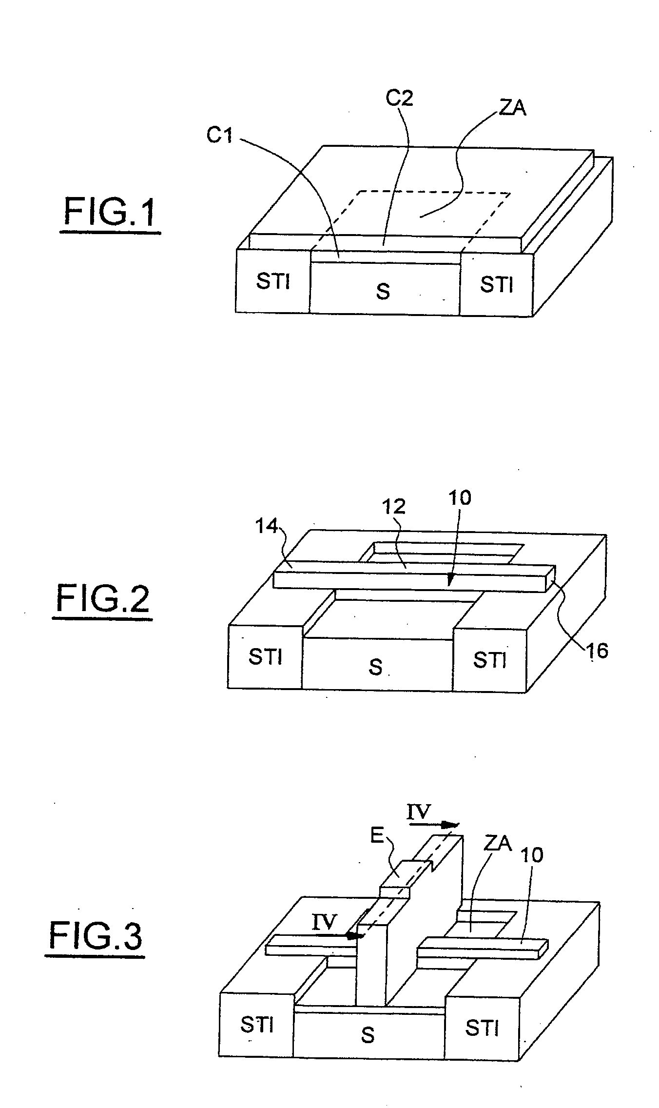
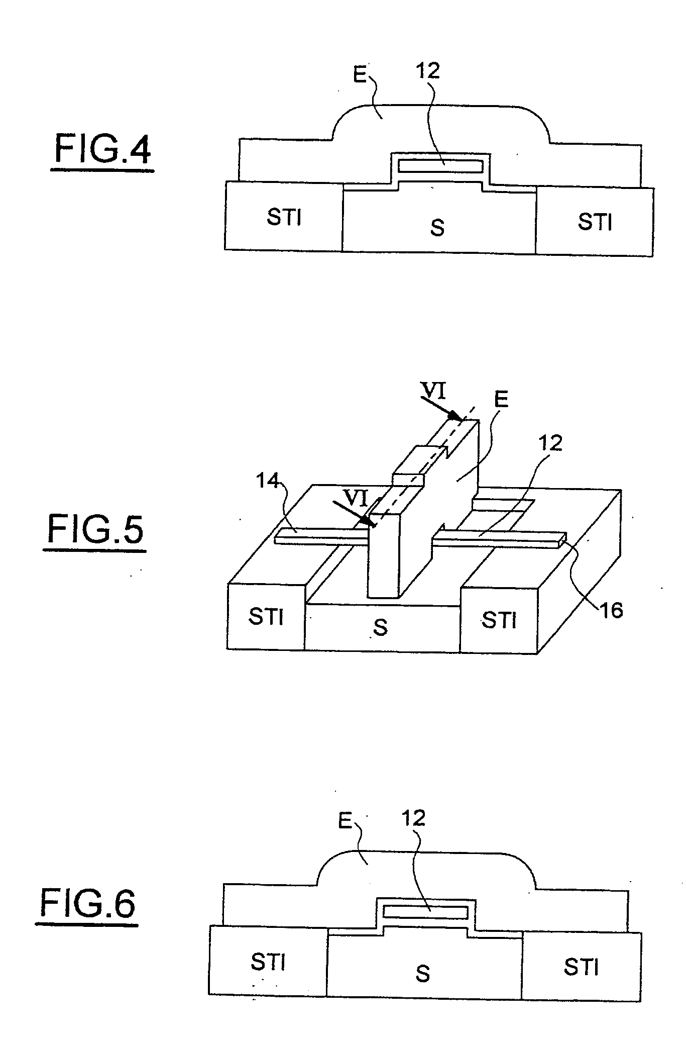
[0037] Referring firstly to FIGS. 1 to 6, the principal phases of an embodiment of a method for fabricating an electromechanical resonator according to the invention will be described.

[0038] As represented in FIG. 1, the starting structure for the production of the resonator consists of a silicon substrate S, in which is formed an active zone ZA surrounded by an insulating region STI (Shallow Trench Isolation).

[0039] On the basis of this structure, a sacrificial-material layer C1, preferably consisting of silicon-germanium (SiGe), is formed by selective epitaxy above the active zone ZA. A silicon layer C2 is then grown by nonselective epitaxy.

[0040] The techniques of growth by selective and nonselective epitaxy are conventional techniques within the scope of a person skilled in the art. They will not therefore be described in detail below. It will, however, be pointed out that these steps make it possible to obtain a localized SiGe layer on the active zone ZA, a monocrystalline-s...


PUM


Abstract

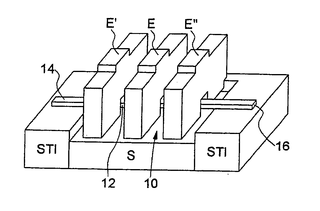
An electromechanical resonator includes a monocrystalline-silicon substrate (S) provided with an active zone (ZA) delimited by an insulating region, a vibrating beam (10) anchored by at least one of its free ends on the insulating region and including a monocrystalline-silicon vibrating central part (12), and a control electrode (E) arranged above the beam and bearing on the active zone. The central part (12) of the beam is separated from the active zone (ZA) and from the control electrode (E).

Description

CROSS-REFERENCE TO RELATED APPLICATION [0001] This application is based upon and claims priority from prior French Patent Application No. 03 09106, filed on Jul. 25, 2003, the entire disclosure of which is herein incorporated by reference. BACKGROUND OF THE INVENTION [0002] 1. Field of the Invention [0003] The invention relates to an electromechanical resonator and to a method for fabricating such a resonator. More particularly, the invention relates to the production of such a resonator in an integrated form, that is to say by using a technology generally used for the production of integrated circuits. [0004] 2. Description of the Related Art [0005] Electromechanical resonators, and in particular those resonators which operate in a bending vibration mode, are conventionally produced in the form of a vibrating element connected to a control electrode, with a detection electrode measuring a characteristic of the integrated circuit, which is associated with the vibration of the vibrat...

Claims


Application Information

Patent Timeline
Patent Type & Authority Applications(United States)
IPC IPC(8): B81B3/00H03H9/24
CPCH03H2009/02511H03H9/2405
Inventor MONFRAY, STEPHANEANCEY, PASCALSKOTNICKI, THOMASSEGUENI, KARIM
Owner STMICROELECTRONICS SRL
Learn More