
Nucleic acid analysis apparatus

Inactive Publication Date: 2005-09-08
HITACHI HIGH-TECH CORP
View PDF10 Cites 9 Cited by
  • Summary
  • Abstract
  • Description
  • Claims
  • Application Information

AI Technical Summary

Benefits of technology

[0005] In the conventional reading technique employing a laser oscillator as the excitation light source and a photomultiplier as the detector, only information at individual points on the DNA chip is obtained. Thus, in order to obtain two-dimensional information about the DNA chip, a mechanism is required for scanning inside the DNA chip. Furthermore, if there are two kinds of fluorescent dye as the object of measurement, two sets of laser oscillators and photomultipliers are required. Thus, in order to read the DNA chip, each measurement site on the DNA chip must be scanned, and, for each measurement site, the light sources and detectors must be switched for measurement as many times as the number of the fluorescent dyes that must be detected, resulting in a longer measurement time. The ever-increasing degree of integration of the DNA chips is also another factor contributing to the extension of measurement time.
[0006] It is therefore an object of the invention to enable each measurement site on a DNA chip to be measured within a short time.
[0008] In accordance with the invention, individual measurement sites on the DNA chip can be measured all at one time. The measurement conditions at each measurement site can be made substantially identical, leading to an improvement in measurement accuracy. The size, cost, and the failure rate of the reading mechanism can be reduced, and virtually no maintenance is required.

Problems solved by technology

Thus, in order to read the DNA chip, each measurement site on the DNA chip must be scanned, and, for each measurement site, the light sources and detectors must be switched for measurement as many times as the number of the fluorescent dyes that must be detected, resulting in a longer measurement time.

Method used


Image

  • Nucleic acid analysis apparatus
  • Nucleic acid analysis apparatus
  • Nucleic acid analysis apparatus

Examples


embodiments

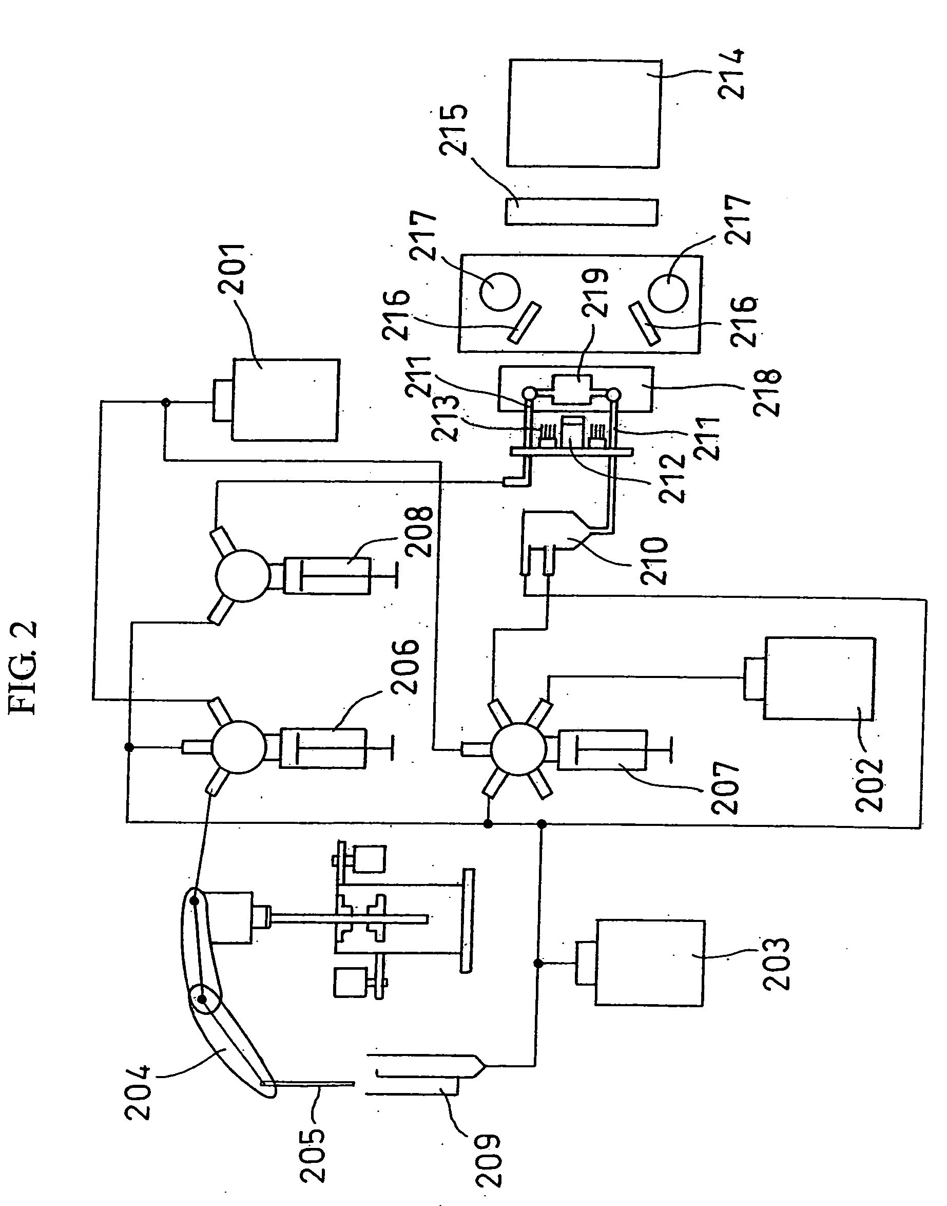
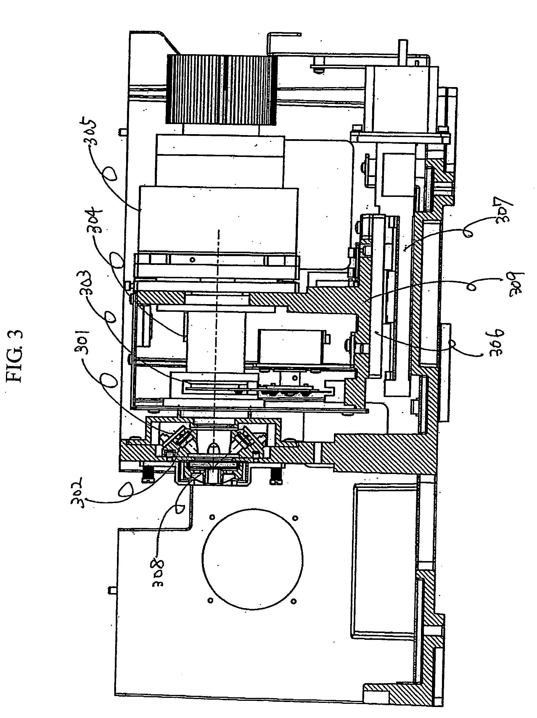
[0019]FIG. 1 shows a broken perspective view of a SNP analysis apparatus in which a DNA chip in accordance with an embodiment of the invention is utilized. The outline of the SNP analysis apparatus is described with reference to FIG. 1.

[0020] SNP analysis apparatuses are mainly used for detecting SNPs of DNA. The SNP stands for single nucleotide polymorphism, and it refers to those genes that differ from one another in only one base. The SNPs are thought to be related to diseases, and searches are vigorously conducted for SNPs related to various diseases.

[0021] The SNP analysis apparatus of the embodiment provides a final output in the following three states: states in which an SNP of interest exists, or does not exist, in a sample DNA in both alleles (“homo”), and a state in which an SNP of interest exists in only one of the alleles (“hetero”). In an example of method for distinguishing among them, a reagent that reacts with and binds to (hybridizes with) a sample having an SNP o...


PUM

PropertyMeasurementUnit
Timeaaaaaaaaaa
Angleaaaaaaaaaa
Distanceaaaaaaaaaa

Abstract

An apparatus measures individual measurement sites on a DNA chip in a short period of time. The DNA chip is irradiated by light-emitting diodes (LEDs) so as to excite fluorescent dye at each measurement site, and fluorescence emitted from the individual measurement sites is detected all at once. Since substantially uniform measurement conditions can be obtained for each measurement site, measurement accuracy increases. The read mechanism requires less space and is less costly, thereby decreasing the failure rate and virtually eliminating the need for maintenance of the apparatus.

Description

BACKGROUND OF THE INVENTION [0001] 1. Field of the Invention [0002] The present invention relates to nucleic acid analysis apparatuses, such as an SNP analysis apparatus for analyzing single nucleotide polymorphism (SNP) of a purified DNA sample. [0003] 2. Description of Related Art [0004] JP Patent Publication (Kokai) No. 2000-131237 A discloses a conventional method and apparatus for reading DNA array chips. The disclosed technology involves moving a DNA chip and an excitation light source relative to each other, scanning the DNA chip using a laser beam of light, and detecting fluorescence with a photomultiplier (PMT), thus reading the DNA chip. SUMMARY OF THE INVENTION [0005] In the conventional reading technique employing a laser oscillator as the excitation light source and a photomultiplier as the detector, only information at individual points on the DNA chip is obtained. Thus, in order to obtain two-dimensional information about the DNA chip, a mechanism is required for scan...

Claims


Application Information

Patent Timeline
IPC IPC(8): G01N21/64C12M1/00C12M1/34C12N15/09C12Q1/68G01N21/78G01N33/53G01N37/00
CPCC12Q1/6834G01N21/6452G01N21/6456G01N2201/062C12Q2565/619
Inventor YAMAMOTO, SHUHEIMAESHIMA, MUNEOHAMA, KATSUNOBUTAKAHASHI, SATOSHI
Owner HITACHI HIGH-TECH CORP
Learn More