Stage apparatus and control method therefor

a stage apparatus and control method technology, applied in the field of stage apparatus and control method therefor, can solve the problems of laser interferometer inoperativeness, deterioration of the control band, and inability to operate, and achieve the effect of reducing misalignmen

Active Publication Date: 2005-09-01
CANON KK
View PDF5 Cites 76 Cited by
  • Summary
  • Abstract
  • Description
  • Claims
  • Application Information

AI Technical Summary

Benefits of technology

[0012] The present invention is conceived as a solution to the problem described above, and has as its object to reduce misalignment occurring when switching between laser interferometers.

Problems solved by technology

However, increasing the length of the reflecting mirror leads to the following problems: (1) In terms of manufacture and installation, it is difficult to achieve a nearly perfectly flat surface; (2) Even where it is possible to achieve a nearly perfectly flat surface, the cost is prohibitive; and (3) as the characteristic value of the reflecting mirror decreases, the band of control deteriorates.
At the same time, the laser interferometer becomes inoperative if the light path is obstructed.
As a result: (4) the positioning of the laser interferometer and the reflecting mirror may be limited by the balance with the other units.
In particular, with respect to the disposition of the laser interferometer and the reflecting mirror for measuring the position in the direction of the optical axis of the projective optical system (hereinafter the “Z axis”), there are many limitations because most of the units are concentrated near the projective lens.
However, because the reflecting mirrors placed in the light paths of the laser interferometers are not perfectly flat but differ in shape from one mirror to the next, simply continuing measurements alone causes misalignments to occur.
As a result, in for example the exposure apparatus, if such misalignments occur along the X, Y axes (that is, in the direction of movement of the X-Y stage (the wafer stage)), they can cause accumulated error, and if such misalignments occur along the Z axis, they can cause focusing error.

Method used


Image

  • Stage apparatus and control method therefor
  • Stage apparatus and control method therefor
  • Stage apparatus and control method therefor

Examples


Embodiment Construction

[0023] Preferred embodiments of the present invention will now be described in detail in accordance with the accompanying drawings.

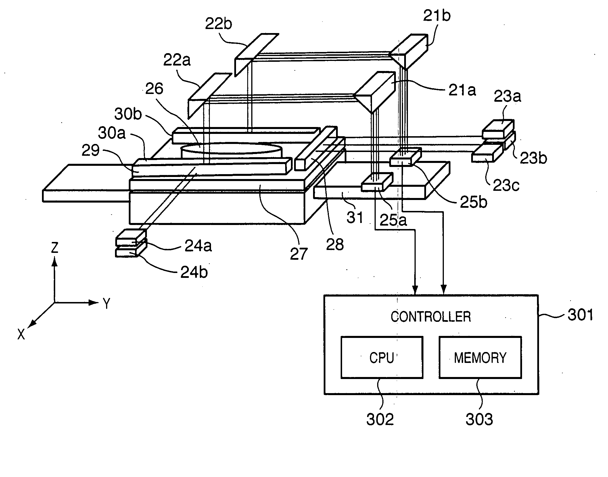
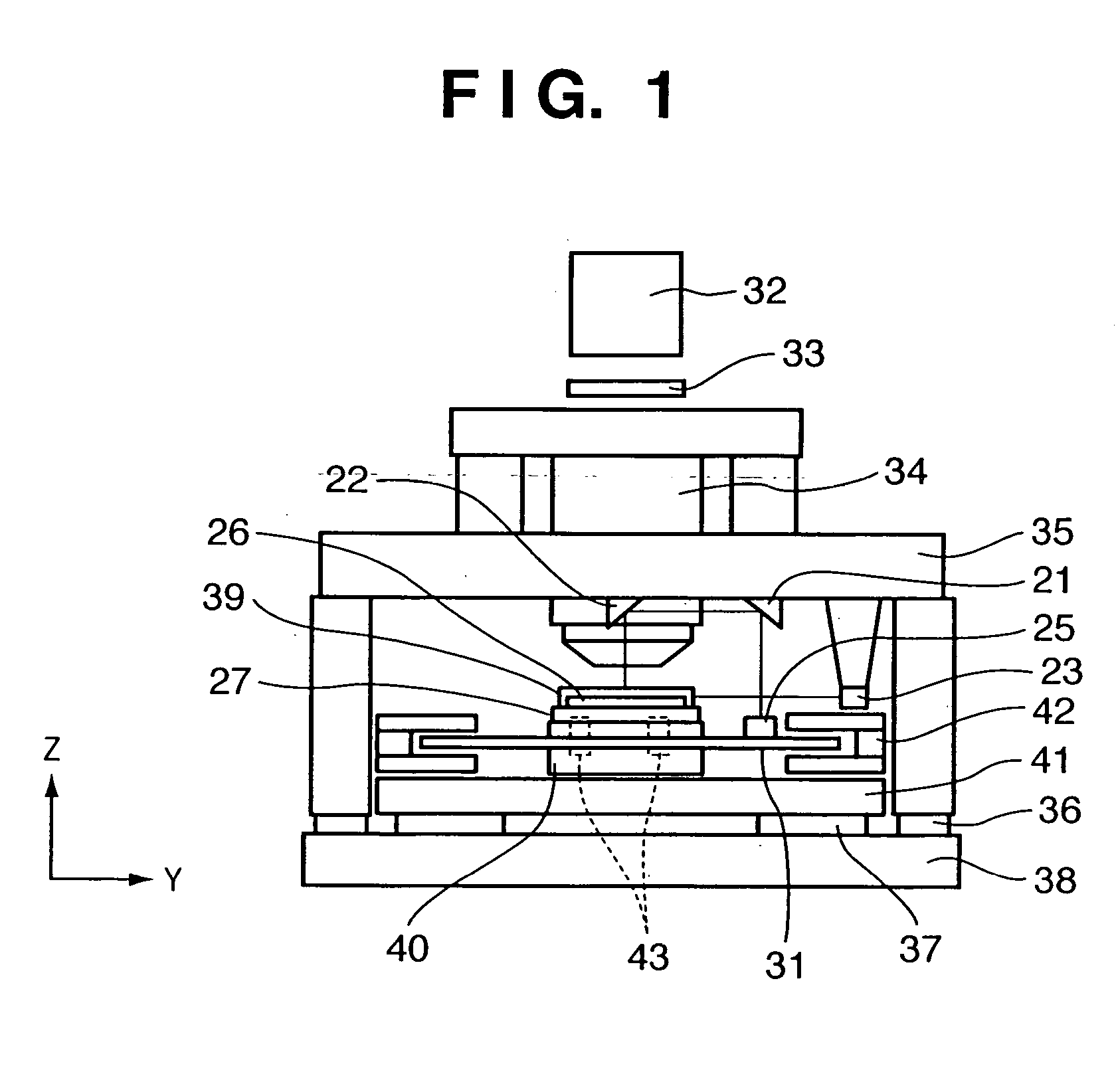
[0024]FIG. 1 is a schematic front view of a semiconductor exposure apparatus according to one embodiment of the present invention. In FIG. 1, an illumination section 32 illuminates a reticule 33 that is an original plate. A pattern to be transferred is drawn on the reticule 33. A projective lens 34 (projective optical system) projects the pattern formed on the reticule 33 onto a wafer, not shown, that is a substrate placed atop a wafer chuck 26. The projective lens 34 is supported by a mirror barrel support 35. A main unit active mount 36 restrains vibration of the mirror barrel support 35 while supporting it and insulating it from vibration from the floor. A positioning table is provided with the main unit active mount 36 and a stage active mount 37.

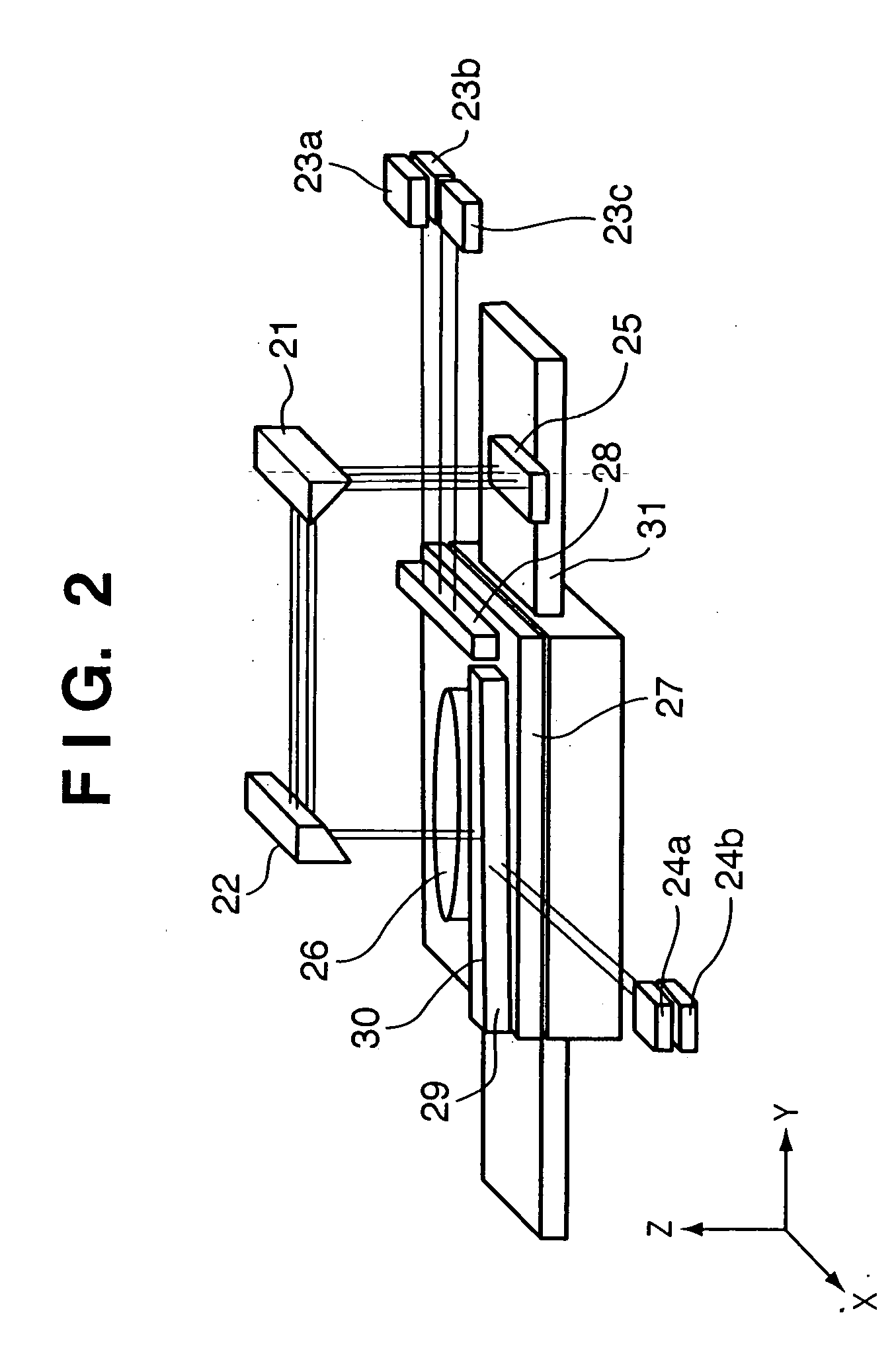
[0025] Fixed mirrors 21, 22 used for Z-axis position measurement are fixedly mounted on the mirror barr...


PUM

PropertyMeasurementUnit
lengthaaaaaaaaaa
shapeaaaaaaaaaa
lengthsaaaaaaaaaa

Abstract

A stage apparatus has a stage movable in a first direction and first and second measurement systems measuring a position of the stage in a predetermined direction. The first and second measurement systems each has a laser interferometer and a mirror system including a first reflecting mirror elongated in the first direction. A measurement value is transferred from one measurement system in use to the other measurement system and the measurement system in use is switched between the first and second measurement systems within a overlapping zone where said first and second measurement system can simultaneously measure the position of the stage. In the switch, the measurement value to be transferred is corrected based on a difference in the lengths of the light paths due to a shape of a surface of the first reflecting mirror of the first and second measurement systems.

Description

FIELD OF THE INVENTION [0001] The present invention relates to a stage apparatus and a control method therefor, and more particularly, to that which can optimally execute position measurement of a stage adapted to carry a semiconductor manufacturing mask or a substrate such as a semiconductor wafer or the like. BACKGROUND OF THE INVENTION [0002] In the photolithography process of semiconductor device manufacturing, an exposure apparatus is used to transfer the fine pattern of a reticule onto a wafer coated with photosensitive material. The measurement of the position of a stage on which such a wafer is placed and the stage drive require a high degree of accuracy, and therefore a high-resolution laser interferometer and a reflecting mirror that is the target of the laser beam are used. In recent years, as semiconductor wafers have increased in diameter, the drive range of the stage has also increased, as has the length of the reflecting mirror. [0003] However, increasing the length o...

Claims


Application Information

Patent Timeline
Patent Type & Authority Applications(United States)
IPC IPC(8): G01B11/00G01B9/02G03F7/20H01L21/027
CPCG03F7/70775
Inventor AKIMOTO, SATOSHI
Owner CANON KK
Why Eureka
Try Eureka