
Reflector lamp having reduced seal temperature

a technology of reflector lamps and seal temperature, which is applied in the field of light sources, can solve the problems of premature lamp failure, exacerbated problem, and typical failure mode of ceramic metal halide sources

Inactive Publication Date: 2005-08-25
OSRAM SYLVANIA INC
View PDF6 Cites 25 Cited by
  • Summary
  • Abstract
  • Description
  • Claims
  • Application Information

AI Technical Summary

Problems solved by technology

For example, a typical failure mode for ceramic metal halide sources occurs as a result of chemical attack by the metal halide fills on the frit materials used to make the electrode seals.
In a conventional reflector lamp structure, this problem is exacerbated because some of the emitted visible radiation is reflected back onto the ceramic metal halide source, and in particular, the electrode seal located in the neck portion of the reflector.
The absorbed energy causes the electrode seal to overheat which in turn increases the rate of chemical attack by the fill on the seal leading to premature lamp failure.

Method used


Image

  • Reflector lamp having reduced seal temperature
  • Reflector lamp having reduced seal temperature
  • Reflector lamp having reduced seal temperature

Examples


Embodiment Construction

[0009] For a better understanding of the present invention, together with other and further objects, advantages and capabilities thereof, reference is made to the following disclosure and appended claims taken in conjunction with the above-described drawings.

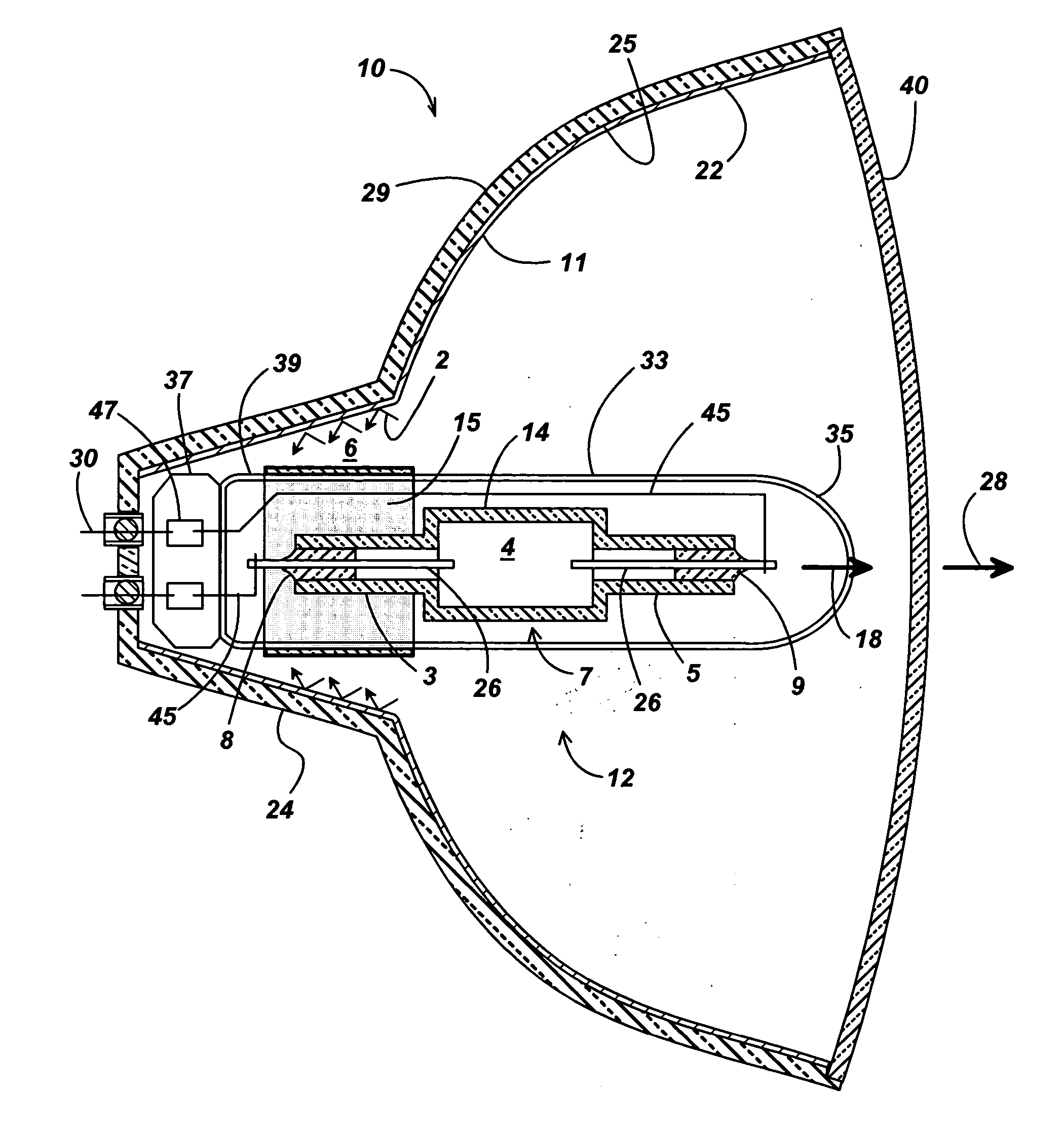
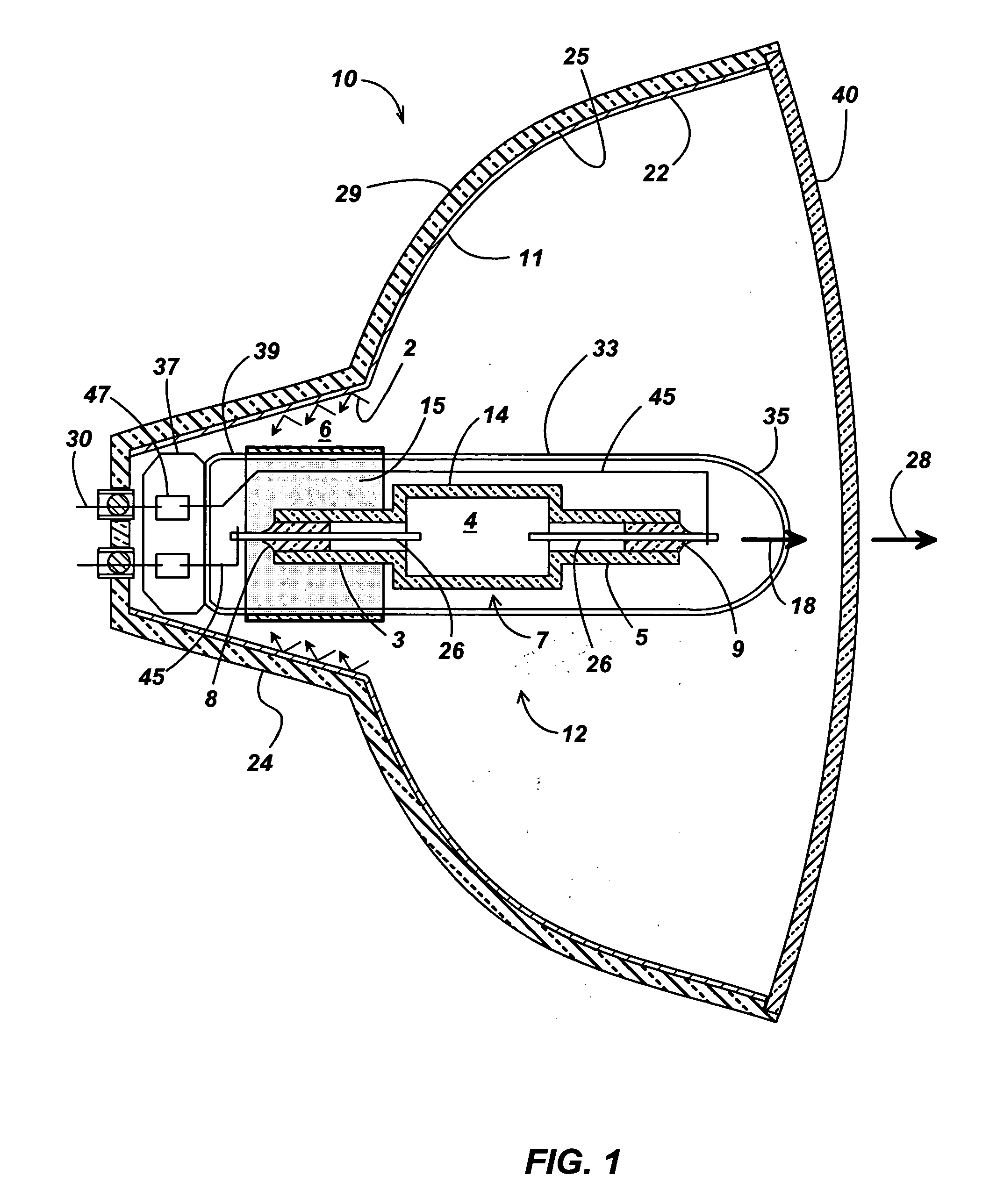
[0010]FIG. 1 is a cross-sectional view of a preferred embodiment of the reflector lamp of this invention. The reflector lamp is comprised of reflector body 10 and light source 12. A lens 40 may or may not be attached to the forward edge of the reflector to enclose the light source 12 within the reflector body 10. The lens may be fused, glued, or similarly coupled to the reflector body as is known in the art. The reflector body 10 is comprised of concave shell 29 and neck 24 which defines neck cavity 6. The shell 29 surrounds the light source 12 to reflect light from the light source 12 onto a field to be illuminated during lamp operation. The reflector body 10 has a reflective surface 11 to reflect the light emitted from light ...


PUM


Abstract

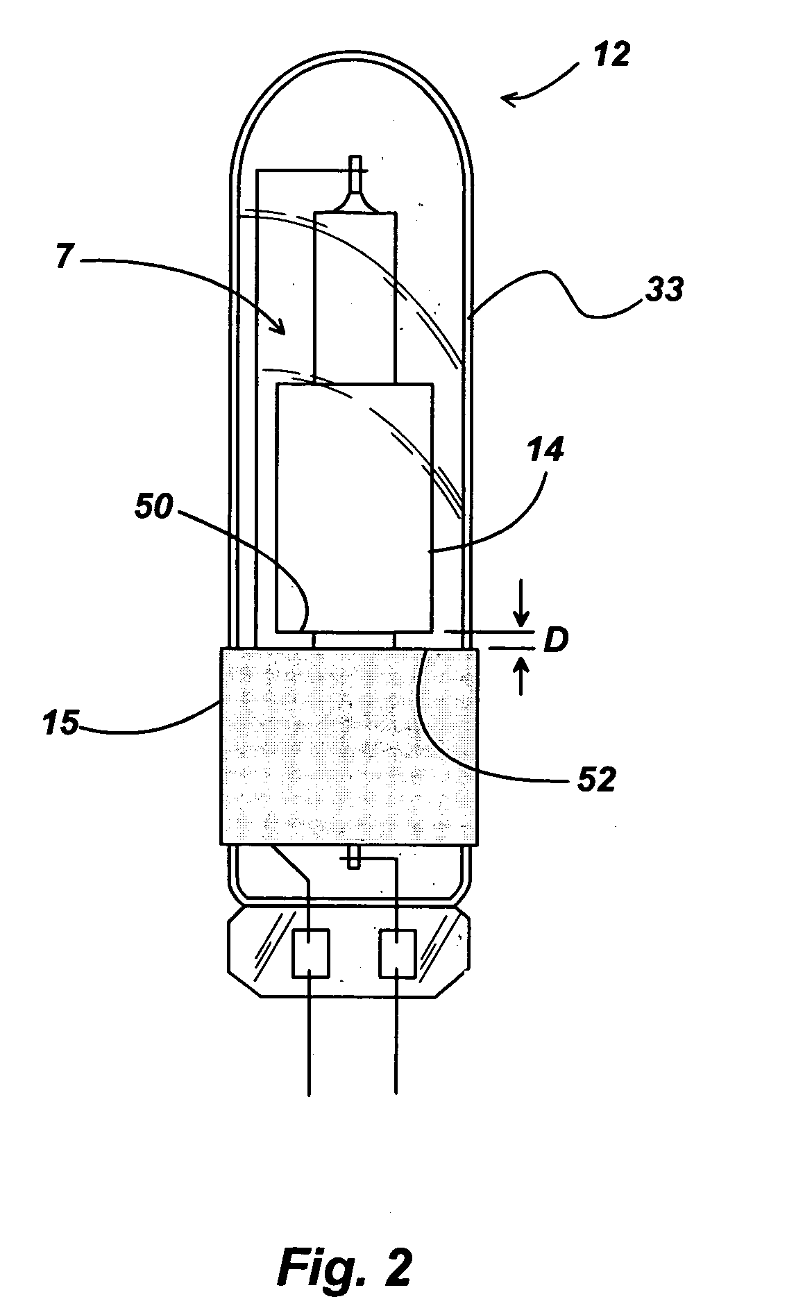
The seal temperature of a reflector lamp having a ceramic metal halide light source is reduced by a light absorbing layer which is provided in a region of the outer jacket adjacent to the electrode seal. Light reflected within the neck cavity of the reflector lamp impinges on the light absorbing layer and is absorbed before it can reach the electrode seal which is at least partially located in the neck of the reflector. The heat from the absorbed light is conducted into the base of the lamp to be dissipated in the socket.

Description

CROSS REFERENCES TO RELATED APPLICATIONS [0001] This application is related to copending application Ser. No. 10 / 120,958, filed Apr. 11, 2002.TECHNICAL FIELD [0002] The present invention is related to light sources that are mounted within a reflector body. More particularly, this invention is related to reflector lamps having a ceramic metal halide light source. BACKGROUND OF THE INVENTION [0003] Ceramic metal halide light sources are comprised of a ceramic discharge vessel (commonly referred to as an arc tube) that is generally made of polycrystalline-alumina. Typical metal halide fills may include mercury, alkali- and alkaline-earth iodides, in particular NaI and CaI2, and rare-earth iodides such as DyI3, TmI3 and HoI3. Xenon or argon are typical gas fills. Tungsten electrodes are used to generate an arc within the discharge vessel. Because electrical power must be supplied to the electrodes, the electrode assemblies must extend through the arc tube wall. In a conventional constru...

Claims


Application Information

Patent Timeline
IPC IPC(8): F21S8/10F21Y101/00H01J5/32H01J5/48H01J5/50H01J61/00H01J61/02H01J61/34H01J61/35H01J61/36H01J61/52H01J61/86
CPCH01J5/50H01J61/35H01J61/34H01J61/52
Inventor GALVEZ, MIGUELLAPATOVICH, WALTER P.
Owner OSRAM SYLVANIA INC
Learn More