
Device and method for testing a membrane electrode assembly

a technology of membrane electrodes and electrode assemblies, which is applied in the direction of instruments, material electrochemical variables, electrochemical generators, etc., can solve the problems of undesired thickness and strong drop in conductivity in the area of leakage, and achieve the effect of short time, saving time, and reducing the accuracy of measuremen

Inactive Publication Date: 2005-08-25
DEUTSCHES ZENTRUM FUER LUFT & RAUMFAHRT EV
View PDF12 Cites 11 Cited by
  • Summary
  • Abstract
  • Description
  • Claims
  • Application Information

AI Technical Summary

Benefits of technology

[0007] In accordance with the invention, contact is made with the first side, and, in particular, electrode side, of the test object (sample) with the first contact device, and, in a corresponding manner, contact is made with the second side of the test object (sample) and, in particular, with the second electrode side of the test object (sample) with the second contact device. A conductivity measurement can then be conducted between the two electrode sides. This is carried out in a location-resolved manner by means of the segmented construction of at least one of the two contact devices, i.e., determined by the arrangement and construction of the individual contact segments. A conductivity measurement can be carried out in a non-destructive manner, so that the inventive device can be integrated in a simple way into the manufacturing process of a membrane electrode assembly.
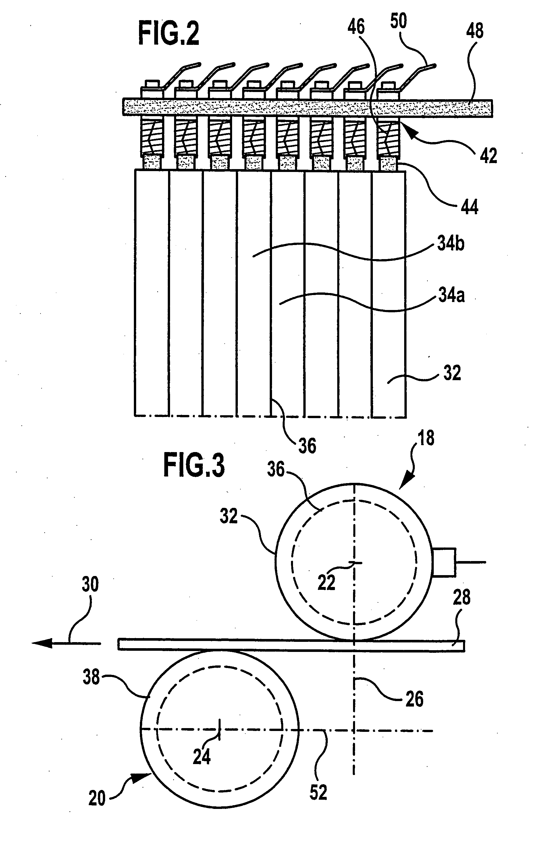
[0020] Provision may be made for the spacing between axes of rollers of the first contact device and the second contact device to be adjustable. In principle, the adjustability can take place in two different directions, namely in the direction of transportation and transversely thereto. In the transverse direction, the adjustability makes it possible for membrane electrode assemblies of different thicknesses to also be passed through. Via the adjustability in the direction of transportation, the current path along the direction of transportation, i.e., the spacing in the direction of transportation between the contact areas in which the second contact device and the first contact device electrically contact the test object, is adjustable via setting of a track length. This determines the resolution with respect to location in the direction of transportation. If, for example, this spacing is large, then a long path can be tested in a short time in the direction of transportation, which thus saves time. With such a long path, there may, however, be a decline in the accuracy of the measurement. Therefore, it may prove expedient, particularly when the test object is to be examined with a high degree of precision, for the spacing between the two contact devices in the direction of transportation to be reduced and, in the ideal case, for no such spacing to exist, i.e., for the axes of the two rollers to lie opposite each other in relation to the direction of transportation.
[0021] To enable electrical contact to be made and transportation of the test object to be carried out simultaneously, it is advantageous for the first contact device and / or the second contact device to be connected by means of sliding contacts to the conductivity measuring device. It is thus possible for signals to be tapped from the first contact device and / or the second contact device, independently of their rotational position.
[0029] Provision may also be made for the impedance between contact areas, offset in relation to a direction of spacing, of the first contact device and the second contact device to be measured. A transverse component of the electrical conductivity (in a surface direction) can thereby also be determined in an impedance-spectroscopic manner, so as to increase the resolution with respect to location.
[0032] In this way, insulating test objects, such as a membrane, can also be tested segmentwise in a location-resolved manner. By testing for a deviation between the charging behavior and the discharging behavior, a leak in a membrane as test object is, for example, detectable. This is due to a change in the dielectric characteristics of the test object between the two contact devices. By charging the contact devices, which, in particular, are constructed as transport rollers, a quasi-impedance measurement can thus be conducted on the test object without a current having to flow through it.

Problems solved by technology

The conductivity sheds light on any possible damage to the membrane such as, for example, a leak, which results in a strong drop in the conductivity in the area of the leak.
Such differences in thickness are undesired, as they result in a different local proton conduction.

Method used


Image

  • Device and method for testing a membrane electrode assembly
  • Device and method for testing a membrane electrode assembly
  • Device and method for testing a membrane electrode assembly

Examples


Embodiment Construction

[0038] The present invention now will be described more fully hereinafter. However, this invention may be embodied in many different forms and should not be construed as limited to the embodiments set forth herein; rather, these embodiments are provided so that this disclosure will satisfy applicable legal requirements. Like numbers refer to like elements throughout.

[0039] An embodiment of an inventive device for testing a membrane electrode assembly, shown in FIG. 1 and generally designated 10 therein, comprises a frame device 12 with opposite frame elements 14 and 16, on which a first contact device 18 and a second contact device 20 are rotatably mounted.

[0040] The first contact device 18 is constructed as a rotatable roller and, in particular, as a transport roller, which is mounted in the frame device 12. The second contact device 20 is likewise constructed as a roller and, in particular, as a transport roller, and is mounted on the frame device 12. The axis of rotation 22 of ...


PUM

PropertyMeasurementUnit
frequencyaaaaaaaaaa
electrically conductiveaaaaaaaaaa
conductivity measuringaaaaaaaaaa

Abstract

In order to create a device for testing a membrane electrode assembly, by means of which fabricated membrane electrode assemblies can be tested in a non-destructive manner, a first contact device is provided for bringing a first electrode side of the test object into electrical contact, a second contact device is provided for bringing a second electrode side of the test object into electrical contact, the first and second contact devices being electrically conductive at least in the contact area, and the first contact device and / or the second contact device having a plurality of electrically conductive contact segments spaced from one another, and a conductivity measuring device is provided for measuring the conductivity of the test object segmentwise in a location-resolved manner.

Description

CROSS-REFERENCE TO RELATED APPLICATIONS [0001] The present application is a continuation application of International Application No. PCT / EP2003 / 007492, filed Jul. 10, 2003, and also claims the benefit of German Application No. 102 32 130.2, filed Jul. 11, 2002, which are incorporated herein by reference in their entirety and for all purposes.FIELD OF THE INVENTION [0002] The invention relates to a device and a method for testing a membrane electrode assembly. The testing may include checking, examining, screening, investigating and measuring a membrane electrode assembly. BACKGROUND OF THE INVENTION [0003] A fundamental problem with membrane electrode assemblies, such as the membrane electrode assemblies of polymer electrolyte membrane fuel cells, is the final inspection, as the membrane can be damaged, and owing to the electrode layers on both sides thereof, this damage is not detectable by visual inspection. [0004] A large number of membrane electrode assemblies, for example, in ...

Claims


Application Information

Patent Timeline
Patent Type & Authority Applications(United States)
IPC IPC(8): G01N27/26H01M8/00H01M8/10
CPCH01M8/1002Y02E60/521H01M8/1018H01M8/1007Y02E60/50
Inventor KAZ, TILLWAGNER, NORBERT
Owner DEUTSCHES ZENTRUM FUER LUFT & RAUMFAHRT EV
Learn More