
MRI system with liquid cooled RF space

a magnetic resonance imaging and liquid cooling technology, applied in superconducting magnets/coils, instruments, magnetic bodies, etc., can solve the problems of increasing the temperature of the patient's body, and increasing the temperature of the cooling fluid. , to achieve the effect of reducing the temperature of the cooling fluid

Inactive Publication Date: 2005-08-18
GE MEDICAL SYST GLOBAL TECH CO LLC
View PDF7 Cites 24 Cited by
  • Summary
  • Abstract
  • Description
  • Claims
  • Application Information

AI Technical Summary

Benefits of technology

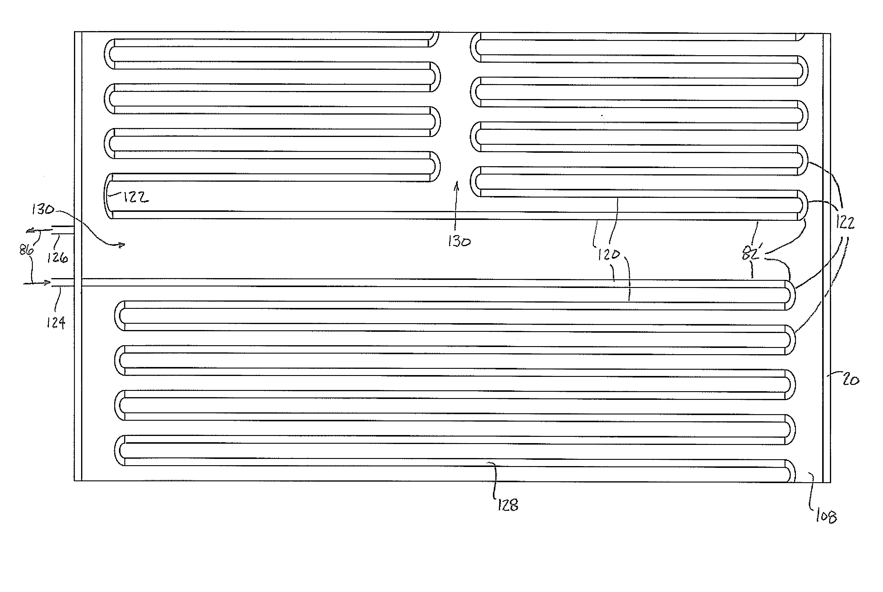
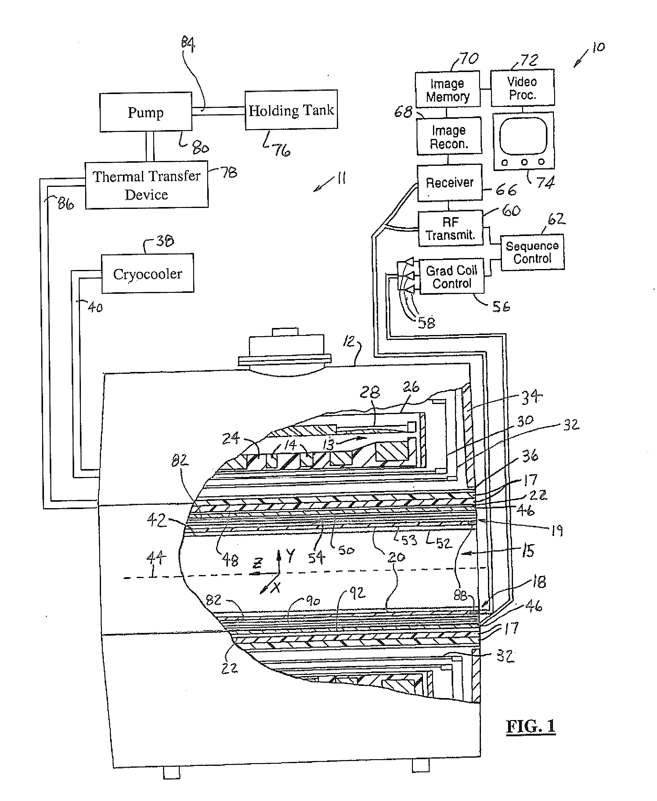
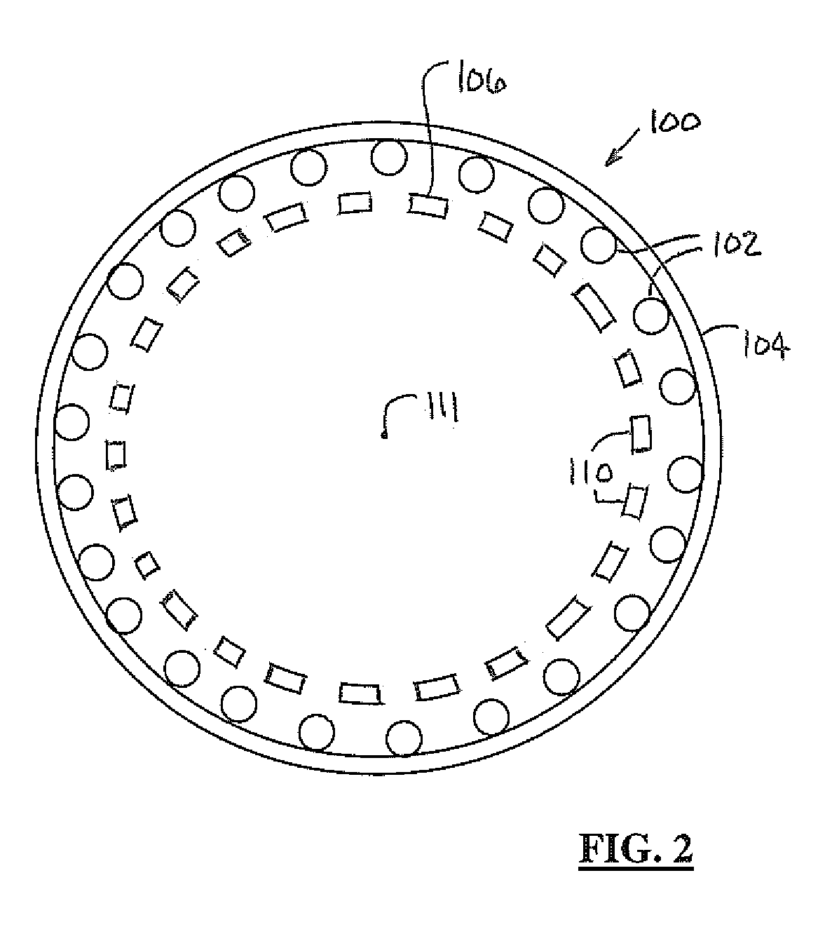
[0010] The present invention provides a radio frequency space cooling system for a magnetic resonance imager system. The cooling system includes a thermal energy transfer device. The energy transfer device reduces the temperature of a cooling fluid within the cooling system. A cooling element is coupled to the energy transfer device and extends along a patient bore between a radio frequency shield and a radio frequency coil of the magnetic resonance imager system. The cooling element has a channel for passage of the cooling fluid.
[0011] The embodiments of the present invention provide several advantages. One such advantage is the provision of active cooling elements within the RF space of an MRI system. The cooling elements prevent thermal energy transfer between a gradient coil assembly and a RF coil of the MRI system. The cooling elements can also be used to remove heat generated in the gradient coil assembly and the RF shield.
[0012] Another advantage provided by an embodiment of the present invention, is the provision of conductive elements arranged in a serpentine like pattern along a patient bore, thereby providing cooling while shielding nMR signals, which are sensitive to the circulation of cooling fluids therein.
[0013] The above-stated advantages allow for increased MRI scanning speeds with reduced operating temperatures, especially within spaces between the gradient coil assembly and the patient bore of a MRI system. The reduced patient bore temperature provides improved patient comfort and safety.

Problems solved by technology

The increase in power consumption by the gradient coil assemblies increases temperatures within the patient volume.
With the ever-increasing power densities within the gradient coil assembly comes increasing inability of the thermal radiation shield to prevent heating of the RF antennae and the patient bore.
Also, for patient comfort and safety there exist temperature operating and rise requirements, as well as overall surface temperature limitations.
Additionally, when an electrically conductive shield is used between the RF coil and the magnetic gradient coil assembly degradation of the resonant electrical properties of the RF circuit and possibly the fidelity of the nMR signals can occur.
An electrically conductive shield may also cause the production of detrimental eddy currents.
As eddy currents produce their own magnetic fields, the magnetic fields produced by these eddy currents can cause interference with the MRI imaging process.
When an infrared reflective shield is used between the RF coil and the RF shield interference of RF wavelengths of interest during an MRI operation can result.
The interference with the RF wavelengths of interest can degrade MRI imaging.
In combination with the aforesaid, MRI systems that have a metallic outer surface on the patient bore may also have RF interference with the nMR signals caused by these metallic surfaces.

Method used


Image

  • MRI system with liquid cooled RF space
  • MRI system with liquid cooled RF space
  • MRI system with liquid cooled RF space

Examples


Embodiment Construction

[0019] In the following figures the same reference numerals will be used to refer to the same components. While the present invention is described with respect to a system for reducing thermal energy transfer from a gradient coil assembly to a RF coil and a patient bore, the present invention may be adapted and applied to various systems including: magnetic resonance imager (MRI) systems, magnetic resonance spectroscopy systems, and other systems that require gradient magnetic fields or radio frequency (RF) fields.

[0020] In the following description, various operating parameters and components are described for one constructed embodiment. These specific parameters and components are included as examples and are not meant to be limiting.

[0021] Also, in the following description the term “RF space” refers the space within an MRI system between and including an RF shield and a magnetic RF coil assembly. The RF space may also include other RF related components, such as a dielectric f...


PUM


Abstract

A radio frequency space cooling system (11) for a magnetic resonance imager system (10) includes a thermal energy transfer device (78). The energy transfer device (78) reduces the temperature of a cooling fluid (86) within the cooling system (11). A cooling element (82) is coupled to the energy transfer device (78) and extends along a patient bore (15) between a radio frequency shield (22) and a radio frequency coil (20) of the magnetic resonance imager system (10). The cooling element (82) has a channel (90) for passage of the cooling fluid (86).

Description

BACKGROUND OF INVENTION [0001] The present invention relates to cooling techniques for magnetic resonance imaging systems. More particularly, the present invention relates to a system for reducing the thermal energy transfer from a gradient coil assembly to an RF coil and a patient bore. [0002] Currently, Magnetic Resonance Imager (MRI) systems have included a superconducting magnet that generates a temporally constant primary magnetic field. The superconducting magnet is used in conjunction with a magnetic gradient coil assembly, which is sequentially pulsed, to create a sequence of controlled gradients in the static magnetic field during an MRI data gathering sequence. The controlled gradients are effectuated throughout a patient imaging volume (patient bore), which is coupled to one or more radio frequency (RF) coils or antennae. The RF coils are located between the magnetic gradient coil assembly and the patient bore. [0003] As a part of a typical MRI sequence, RF signals of sui...

Claims


Application Information

Patent Timeline
IPC IPC(8): G01R33/34G01R33/422H01F6/04H01F27/02
CPCG01R33/34046H01F27/025H01F6/04G01R33/422
Inventor WEYERS, DANIEL J.LINZ, ANTON M.MCKINNON, GRAEME C.BOSKAMP, ED B.DACHNIWSKYJ, ROMAN I.SELLERS, MICHAEL B.MANTON, ANTHONY
Owner GE MEDICAL SYST GLOBAL TECH CO LLC
Learn More