Method for producing spacer for flat panel display

Inactive Publication Date: 2005-08-18
TDK CORPARATION
View PDF8 Cites 3 Cited by
  • Summary
  • Abstract
  • Description
  • Claims
  • Application Information

AI Technical Summary

Benefits of technology

[0013] For these sintered bodys, a resistivity of 1.0×10⁶ to 1.0×10¹¹ Ω·cm, which is preferable as a spacer for a flat panel display, can easily be obtained. For the sintered body, other physical properties are favorable as a spacer for a flat panel display.
[0028] According to the present invention, a collapse resistance can be imparted to the green sheet in a stage after binder removal and before sintering. The green sheet having the collapse resistance has excellent handling characteristics. The green sheet having the collapse resistance can be loaded thereon with a loading member for inhibiting occurrence of warpage during sintering. The present invention is particularly effective for ceramics compositions containing MgO, for which collapsability has been observed.

Problems solved by technology
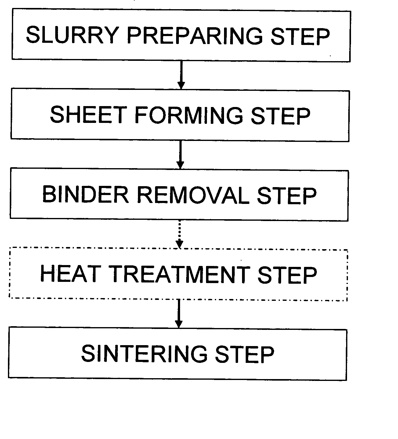
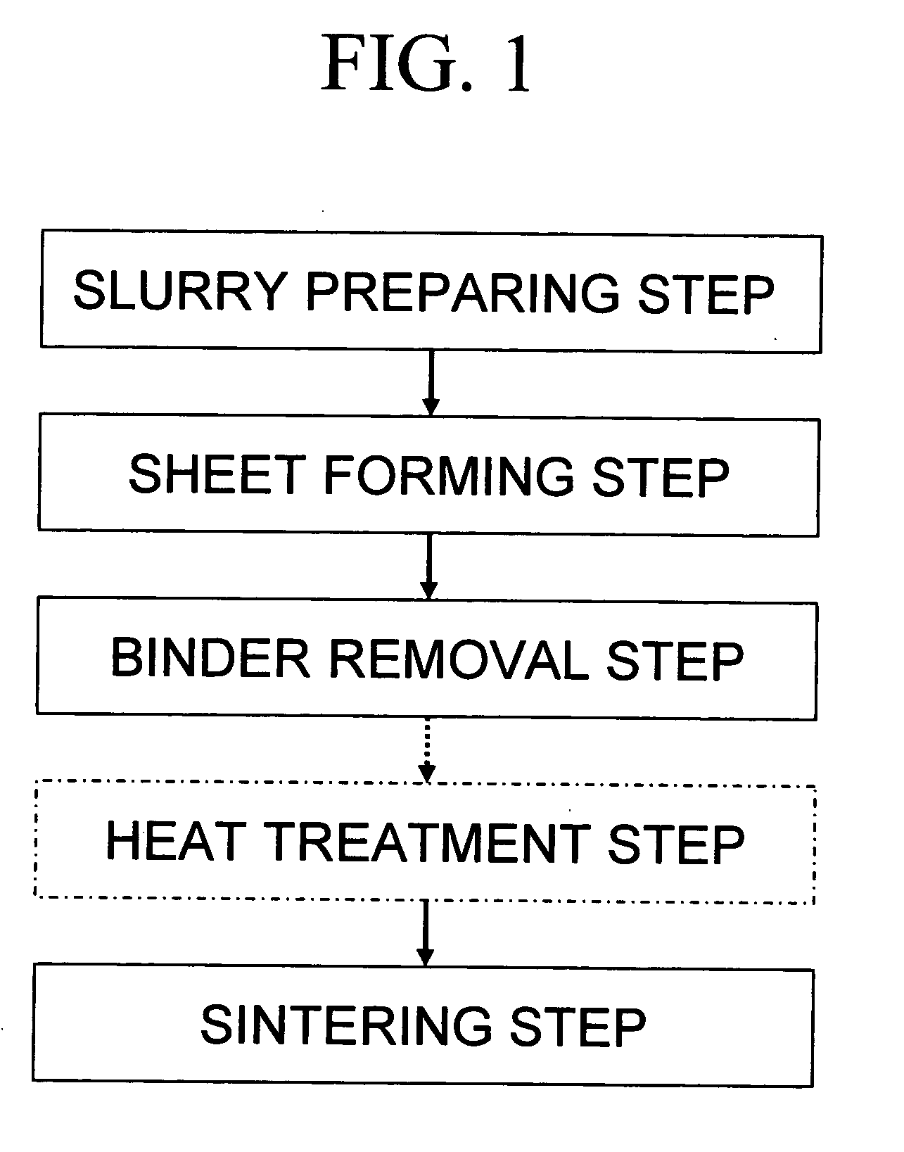
If an arrangement of spacers gets out of order due to the compressive force or other factor, emitted electrons are deflected, and thus visible defects are raised on a display.
However, a sheet method in which the sheet is fabricated and then sintered in this way has a problem such that warpage tends to occur during sintering if the sheet has a small thickness of approximately 100 to 350 μm.
If warpage occurs, a desired flatness cannot be obtained even if polishing is performed, or much time is required for polishing.

Method used


Image

  • Method for producing spacer for flat panel display
  • Method for producing spacer for flat panel display
  • Method for producing spacer for flat panel display

Examples


example 1

[0078] The present invention will be described below based on specific Examples.

[0079] A TiC powder (mean particle size: approximately 0.5 μm, the content of carbon is 19% or greater, of which 1% or less is represented by free graphite), a TiO2 powder (mean particle size: approximately 1.7 μm) and an Al2O3 powder (mean particle size: approximately 0.5 μm) were weighed to TiC: 11.70 mol %, TiO2: 1.81 mol % and Al2O3: 86.49 mol %, and the powders were milled and mixed by a wet process using a ball mill to obtain a raw material powder for slurry.

[0080] A binder, a dispersant, a plasticizer and a solvent were added to the raw material powder for slurry according to the details described below, and they were mixed by a ball mill to prepare a slurry for forming a sheet.

[0081] binder: polyvinyl butyral resin . . . 3 wt %

[0082] dispersant: graft polymer anionic dispersant . . . 2 wt %

[0083] plasticizer: phthalate (e.g. BPBG) . . . 3 wt %

[0084] solvent: alcohol (e.g. ethanol)+aromatic ...

example 2

[0091] An Al2O3 powder (mean particle size: approximately 0.5 μm), a TiO2 powder (mean particle size: approximately 1.7 μm) and an MgO powder (mean particle size: approximately 5.8 μm) were weighed to Al2O3: 30.38 mol %, TiO2: 12.51 mol % and MgO: 57.11 mol %, and the powders were milled and mixed by a wet process using a ball mill to obtain a raw material powder for slurry.

[0092] A binder, a dispersant, a plasticizer and a solvent were added to the raw material powder for slurry according to the details described below, and they were mixed by a ball mill to prepare a slurry for forming a sheet.

[0093] binder: polyvinyl butyral resin . . . 3 wt %

[0094] dispersant: graft polymer anionic dispersant . . . 2 wt %

[0095] plasticizer: phthalate (e.g. BPBG) . . . 3 wt %

[0096] solvent: alcohol (e.g. ethanol)+aromatic solvent (e.g. toluene) . . . 51.25 wt %

[0097] The slurry thus obtained was used to fabricate a green sheet having a thickness of approximately 150 μm by the doctor blade me...


PUM

PropertyMeasurementUnit
Temperatureaaaaaaaaaa

Abstract

By minimizing polishing after sintering, there provided a method for producing a spacer for a flat panel display, which can reduce the processing man-hour and processing cost. A green sheet is prepared from a slurry including a predetermined raw material powder and a binder, the binder is removed from the green sheet, and the binder removed green sheet is sintered with a loading member loaded thereon, which has a surface of a predetermined flatness contacting the green sheet. Preferably, the spacer contains TiC and / or TiO2 and Al2O3 with a composition consisting essentially of 5.0 to 16.0 mol % of TiC, 0.5 to 20.0 mol % of TiO2, and the balance being substantially Al2O3, or contains TiC and / or TiO2, MgO and Al2O3 with a composition consisting essentially of 5.0 to 16.0 mol % of TiC, 0.5 to 20.0 mol % of TiO2, 80.0 mol % or less of MgO and the balance being substantially Al2O3.

Description

BACKGROUND OF THE INVENTION [0001] 1. Field of the Invention [0002] The present invention relates to a method suitable for producing a spacer for a flat panel display using a sheet method. [0003] 2. Description of the Related Art [0004] Thin and light flat displays are known as displays alternative to bulky and heavy cathode ray tubes (CRT). Field emission displays (FED) are known as one type of flat displays. The FED is a self-luminous flat display applying a conventional CRT, and its principle of display of images is similar to that of the CRT. The FED comprises a cathode structure having a large number of cathodes (field emission elements) arranged in a two-dimensional form, in which electrons emitted from the cathodes under an environment of reduced pressure (e.g. 10−5 Torr or less) are accelerated and collided against targeted fluorescent pixel areas to form a luminous image (e.g. Japanese Patent Laid-Open No. 2001-68042). [0005] The FED comprises two flat glass base plates: a ...

Claims


Application Information

Patent Timeline
IPC IPC(8): H01J9/18H01J9/24
CPCH01J9/242H01J2329/864H01J2329/866H01J2329/8655H01J2329/8645A63H33/006F24F8/10
Inventor KUBO, KEIKOHITOMI, ATSUSHIKAWAGUCHI, YUKIOSAWADA, HIROAKIHOSOKAWA, MIO
Owner TDK CORPARATION
Why Eureka
Try Eureka