
Use of powder metal sintering/diffusion bonding to enable applying silicon carbide or rhenium alloys to face seal rotors

a technology of diffusion bonding and powdered metal, which is applied in the direction of sliding contact bearings, mechanical equipment, transportation and packaging, etc., can solve the problems of brittle monolithic silicon carbide (sic), inability to apply sic, and high cost of monolithic ceramic fabrication, etc., to achieve high thermal conductivity material, high temperature and stress, and improved operation

Inactive Publication Date: 2005-08-11
HONEYWELL INT INC
View PDF22 Cites 6 Cited by
  • Summary
  • Abstract
  • Description
  • Claims
  • Application Information

AI Technical Summary

Benefits of technology

The resulting face seal rotor exhibits enhanced thermal conductivity, toughness, and reduced risk of fracture, leading to increased operational life and reduced maintenance costs by effectively managing thermal and physical stresses, and allowing for cost-effective production without the brittleness of monolithic ceramics.

Problems solved by technology

However, monolithic silicon carbide (SiC) can be brittle and is generally not used in some aerospace equipment when there are higher rotation speeds and stresses.
In addition, conventional techniques of coating steel seal rotors with particulate ceramics are not capable of applying SiC because its melting and / or oxidation temperature can be exceeded by such techniques.
Furthermore, fabrication of monolithic ceramics is expensive.
They are difficult to machine and are susceptible to fracture as they are very notch sensitive.
These higher temperatures can reduce the life of both the carbon stator and the face seal assembly.
Although existing designs are safe and reliable, sometimes the carbon stator may fail unexpectedly and the component in which it operates, usually a gas turbine engine starter, must be replaced or repaired.
Such unplanned replacements or repairs are expensive, cause unit downtime, and increase operating costs.

Method used


Image

  • Use of powder metal sintering/diffusion bonding to enable applying silicon carbide or rhenium alloys to face seal rotors
  • Use of powder metal sintering/diffusion bonding to enable applying silicon carbide or rhenium alloys to face seal rotors

Examples


Embodiment Construction

)

[0019] The detailed description set forth below in connection with the appended drawings (if any) is intended as a description of presently-preferred embodiments of the invention and does not represent the only forms in which the present invention, materials, and / or processes may be constructed and / or utilized. The description sets forth the functions and the sequence of steps for constructing and operating the invention in connection with the illustrated embodiments. However, it is to be understood that the same or equivalent functions and sequences may be accomplished by different embodiments that are also intended to be encompassed within the spirit and scope of the invention.

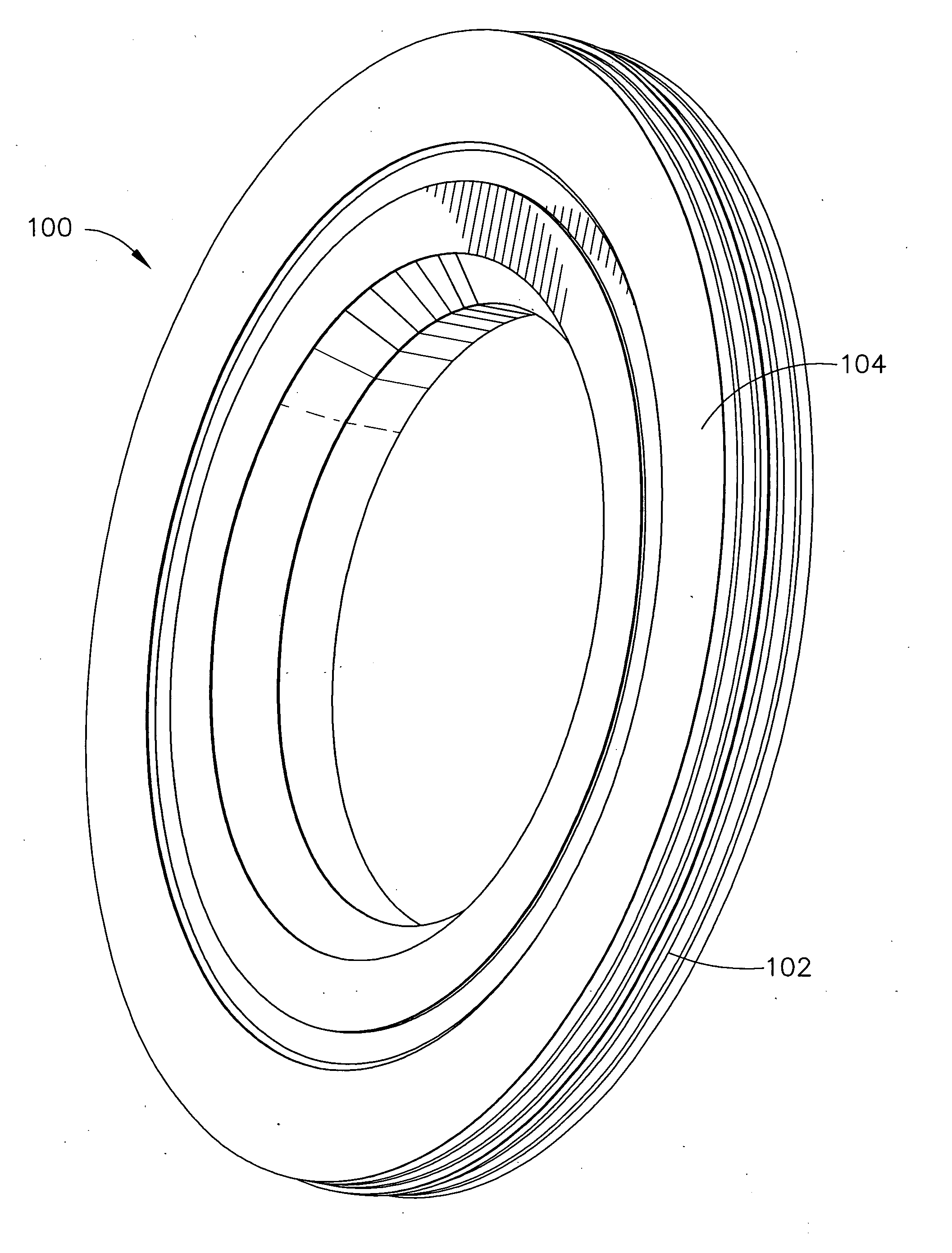
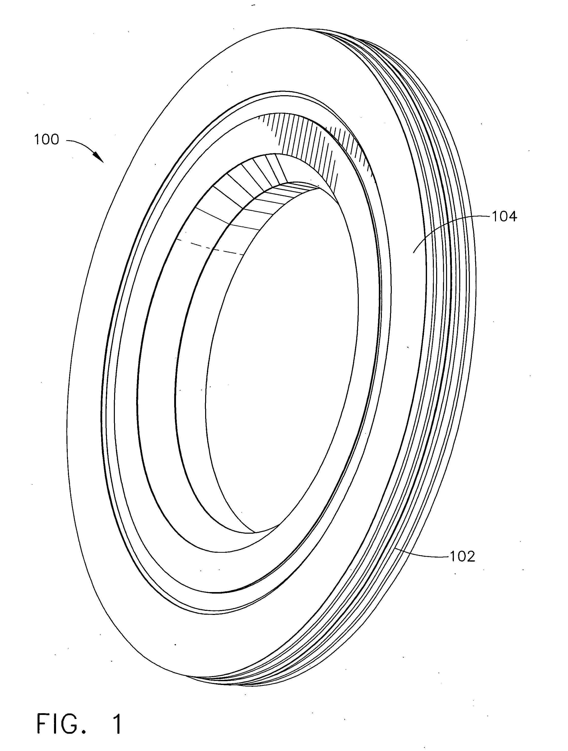
[0020] As shown in FIG. 1, face seal rotor 100 may have a substrate 102 that provides support for a face 104. The face 104 provides one half of a seal (in conjunction with a stator, not shown). The face is where friction may develop and heat and stress may occur. The face 104 provides the operating surface...


PUM

PropertyMeasurementUnit
melting pointaaaaaaaaaa
refractoryaaaaaaaaaa

Abstract

A method for making aerospace face seal rotors reinforced by rhenium metal, alloy, or composite in combination with silicon carbide or other ceramic. The resulting rotor also is disclosed. Ceramic grains, preferably silicon carbide (SiC), are mixed with powdered metallic (PM) binder that may be based on a refractory metal, preferably rhenium. The mixture is applied to a rotor substrate. The combined ceramic-metal powder mixture is heated to sintering temperature under pressure to enable fusion of the ceramic in the resulting metal-based substrate. A load may then be applied under an elevated temperature. The resulting coated rotor can exhibit high hot hardness, increased durability and / or high hot wear resistance, as well as high thermal conductivity.

Description

CROSS-REFERENCES TO RELATED APPLICATIONS [0001] This patent application is related to and priority is claimed to: U.S. Provisional Application Ser. No. 60 / 384,631 filed May 31, 2002 for Use of Powdered Metal Sintering / Diffusion Bonding to Enable Applying Silicon Carbide or Rhenium Alloys to Face Seal Rotors. This application is also a continuation-in-part of U.S. patent application Ser. No. 10 / 138,090 filed May 3, 2002 for Oxidation and Wear Resistant Rhenium Metal Matrix Composite and U.S. patent application Ser. No. 10 / 138,087 filed May 3, 2002 for Oxidation Resistant Rhenium Alloys which applications are all incorporated by reference. [0002] This patent application incorporates the following patent applications by reference but claims no priority to any of them: U.S. Provisional Application 60 / 384,737 filed on May 31, 2002 for Reduced Temperature And Pressure Powder Metallurgy Process For Consolidating Rhenium Alloys; and U.S. patent application Ser. No. 10 / 243,445 filed Sep. 13,...

Claims


Application Information

Patent Timeline
Patent Type & Authority Applications(United States)
IPC IPC(8): B22F7/00B22F7/08C22C32/00F16C17/24F16C33/12F16J15/34H02K7/02H02K7/08H02K7/09
CPCB22F7/008Y10T428/30B22F2998/00B22F2998/10C22C32/0063F16C17/24F16J15/3496H02K7/025H02K7/08H02K7/09Y02E60/16B22F7/08Y10T428/12139Y10T428/2995Y10T428/31Y10T428/12771F16C33/121C22C32/00B22F1/0003B22F3/10B22F3/14B22F2207/20B22F1/12
Inventor GIESLER, WILLIAM L.ADAMS, ROBBIE J.
Owner HONEYWELL INT INC
Learn More