Rotary magnetic head drum apparatus
a rotary magnetic head drum and head drum technology, applied in the field of helical scan type magnetic recording and reproducing apparatus, can solve the problems of not taking into account the accuracy of alignment and adjustment in the prior art, and achieve the effect of improving alignment accuracy, improving accuracy, and easy to achieve fine adjustmen
- Summary
- Abstract
- Description
- Claims
- Application Information
AI Technical Summary
Benefits of technology
Problems solved by technology
Method used
Image
Examples
embodiment 1
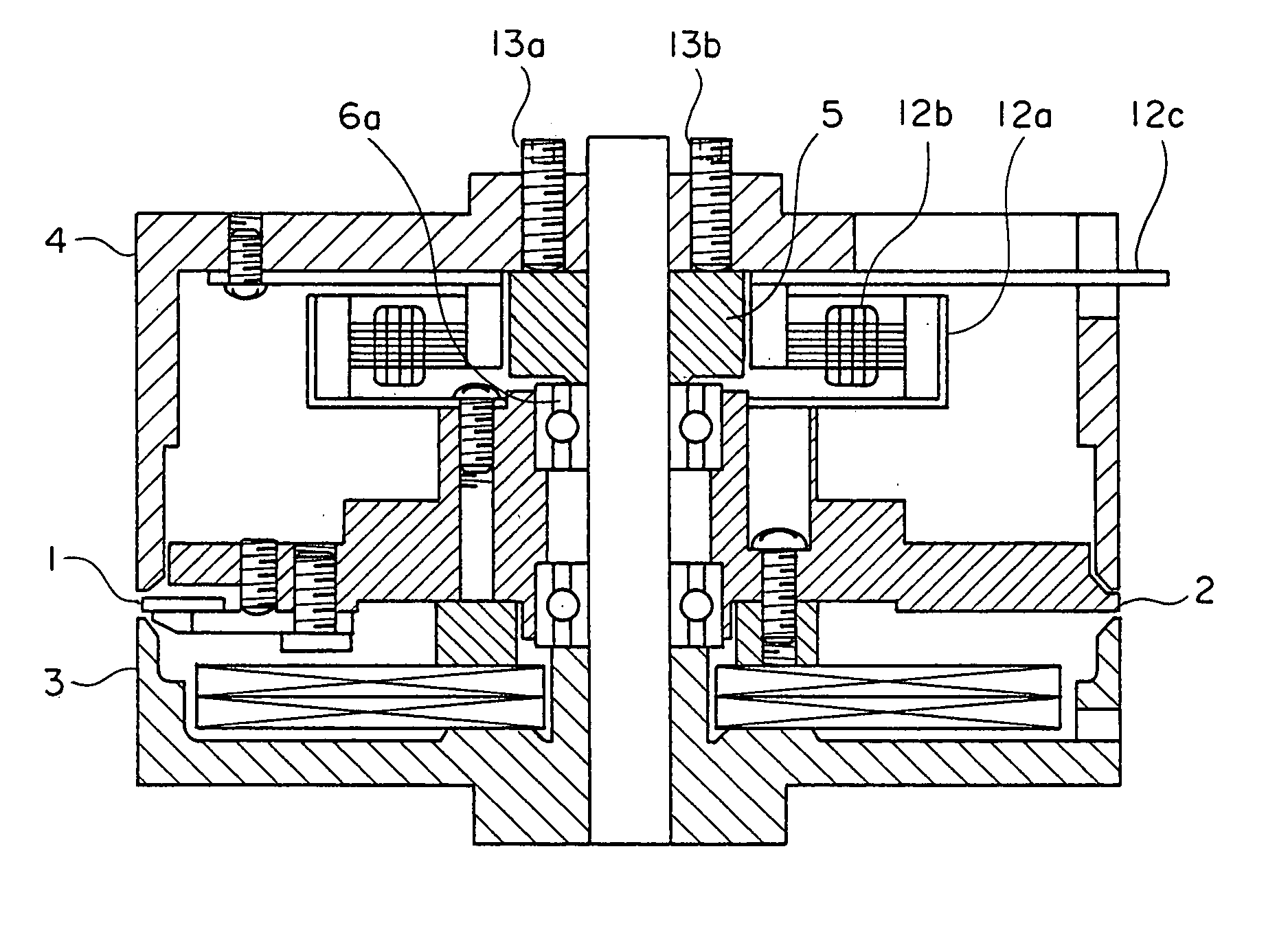
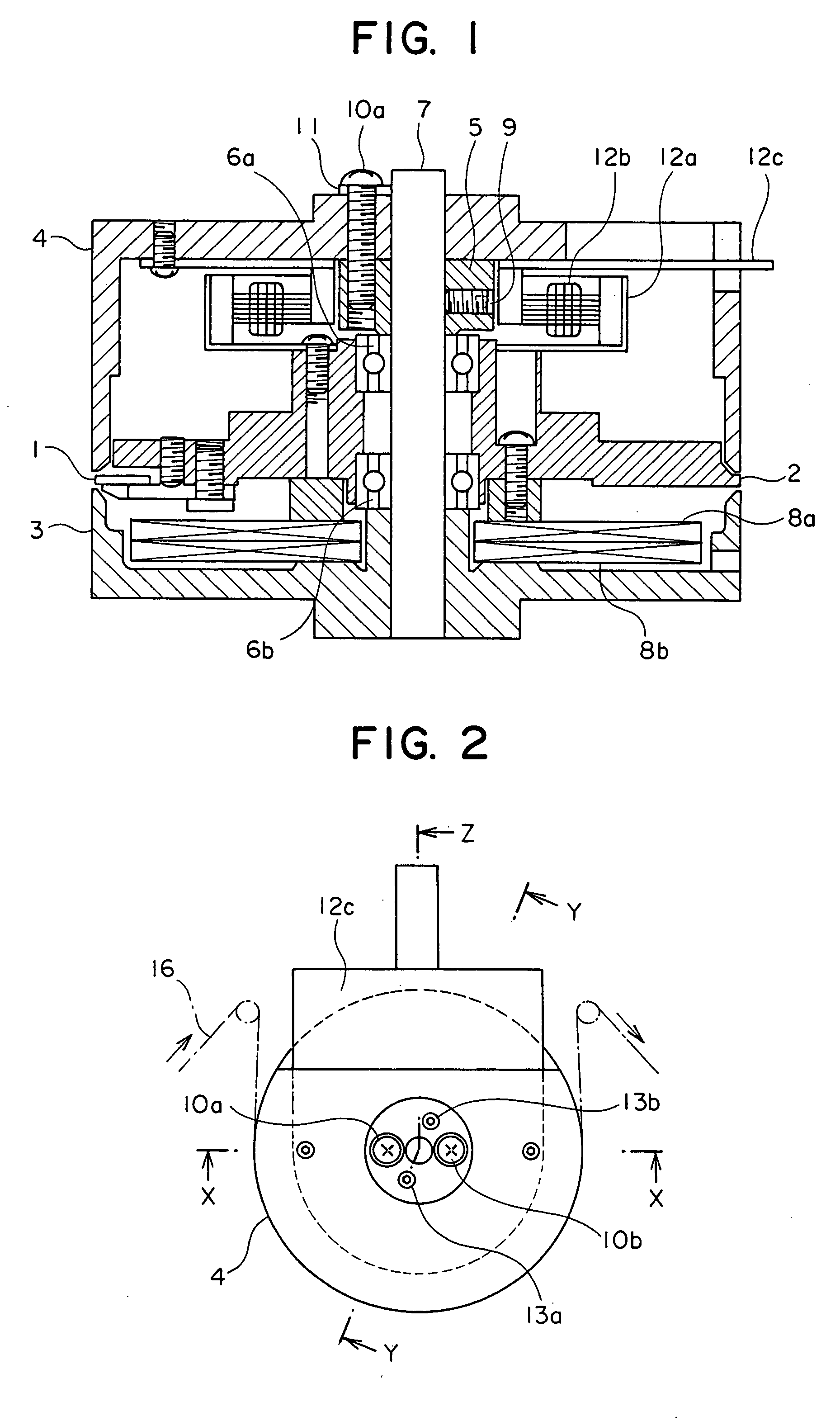
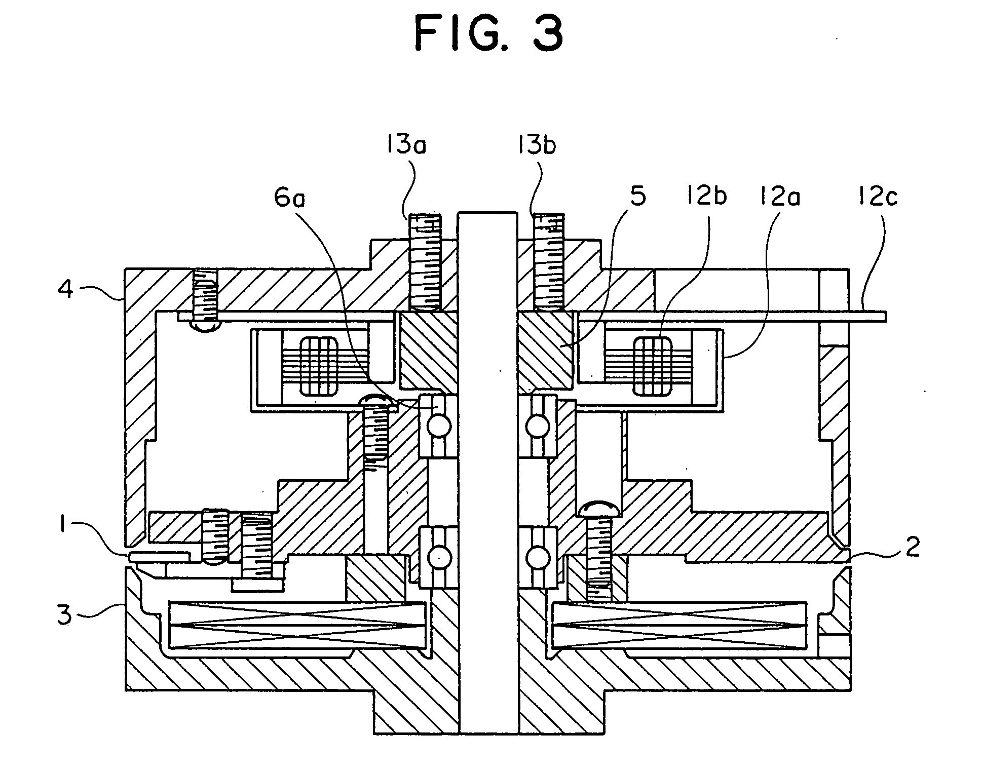
[0027] FIGS. 1 to 4 show a first embodiment of a rotary magnetic head drum apparatus in accordance with the present invention. FIG. 2 is a plan view of the present embodiment, FIG. 1 is a cross sectional view along a line X-Z and FIG. 3 is a cross sectional view along a line Y-Y in FIG. 2. FIG. 4 is a cross sectional view for explaining a fine adjusting operation.
[0028] In FIGS. 1 and 2, a shaft 7 is pressure inserted to a lower fixed drum 3. Reference numeral 2 denotes a center rotating drum. The center rotating drum mounts a magnetic head 1 thereon, and is controlled at a predetermined rotational speed so as to rotate around the shaft 7. Reference symbols 6a and 6b denote a ball bearing. A preload metal fitting 5 is fixed to the shaft 7 by a locking screw 9, and applies a preload to the ball bearings 6a and 6b. Reference symbol 12a denotes a motor rotor. The motor rotor 12a is mounted to an upper end surface portion of the center rotating drum. Reference symbol 12b denotes a moto...
embodiment 2
[0035]FIGS. 5 and 6 show a second embodiment of the rotary magnetic head drum apparatus in accordance with the present invention. FIG. 6 is an enlarged cross sectional view of a part of the locking screw 13a in a cross sectional view shown in FIG. 5. The same reference numerals are attached to the common portions to those in FIGS. 1 to 3.
[0036]FIG. 5 shows a structure in which a motor stator 12d is fastened together with the upper fixed drum 4 at a time of fastening the upper fixed drum 4 to the preload metal fitting 5. FIG. 6 is a partly cross sectional view of the locking screw 13a in the embodiment shown in FIG. 5, and shows with exaggeration a motion of the upper fixed drum 4 in the case of increasing the screwing amount of the locking screw 13a. The state before adjustment is shown by a solid line, and the upper fixed drum 4b after adjustment is shown by a two-dot chain line.
[0037] In the second embodiment, the structure is made such that the motor stator 12d is fastened toge...
embodiment 3
[0038]FIG. 7 shows a third embodiment of the rotary magnetic head drum apparatus in accordance with the present invention, and corresponds to a cross sectional view along a line X-X in FIG. 2.
[0039]FIG. 7 shows a preferable positional relation between the upper fixed drum and the outer peripheral surface of the lower fixed drum. In other words, in the input side of the tape, the outer periphery of the lower end portion of the upper fixed drum is slightly (0.001 mm to 0.005 mm) moved backward with respect to the outer periphery of the lower fixed drum, and in the output side of the tape, the outer periphery of the lower end portion of the upper fixed drum is slightly protruded with respect to the outer periphery of the lower fixed drum. In FIG. 7, the above structure is shown with exaggeration, the state before adjustment (the outer peripheral surfaces of the upper and lower drums are at the same height position) is shown by a one-dot chain line, and an upper fixed drum 4c after adj...
PUM
| Property | Measurement | Unit |
|---|---|---|
| diameter | aaaaa | aaaaa |
| diameter | aaaaa | aaaaa |
| displacement | aaaaa | aaaaa |
Abstract
Description
Claims
Application Information
 - R&D
- Intellectual Property
- Life Sciences
- Materials
- Tech Scout
- Unparalleled Data Quality
- Higher Quality Content
- 60% Fewer Hallucinations
Browse by: Latest US Patents, China's latest patents, Technical Efficacy Thesaurus, Application Domain, Technology Topic, Popular Technical Reports.
© 2025 PatSnap. All rights reserved.Legal|Privacy policy|Modern Slavery Act Transparency Statement|Sitemap|About US| Contact US: help@patsnap.com


