Method and apparatus for creating variable delay

a delay and variable technology, applied in the field of test and measurement systems, can solve the problem of limited maximum speed of operation

Inactive Publication Date: 2005-08-04
SYNTHESYS
View PDF5 Cites 26 Cited by
  • Summary
  • Abstract
  • Description
  • Claims
  • Application Information

AI Technical Summary

Benefits of technology

[0008] Generically, variable delay functions are devices that provide a programmable amount of delay insertion into a data or trigger signal path. This translates, for example, to the rising / falling edge of an input signal being delayed at the output by varying amounts of delay as a function of the variable delay amount setting. The present invention provides for creating variable delay into a data or trigger signal path that operates with fine delay resolution at high frequencies and that covers a delay range which allows a corresponding device to be utilized as a delay vernier for a larger delay range structure.
[0010] An advantage provided by the present invention is that the variable delay function is accomplished in a manor that is quick to make setting changes and is compensated for temperature variations.
[0011] The present invention accepts a signal with triggering edges to be delayed at its input and then outputs a copy of this signal with the edges delayed as a function of an additional further input control. The delay mechanism is the result of summing two or more copies (taps) of the input signal where a known delay is inserted between the taps of the input signal as well as a finite bandwidth of edge transition and each tap's amplitude can be adjusted before the signals are summed. By adjusting the relative amplitudes of the different taps of the signal before they are summed, the resulting summed signal can reproduce the input signal at programmable delay shifts in the range defined by the fixed delay between the first input tap and the last input tap. Changing the amount of delay is simply provided by changing the gain / attenuation coefficients to the different taps to be summed. The maximum speed of operation is limited by what gain / attenuation process can be used as well as the summing process to be used.

Problems solved by technology

The maximum speed of operation is limited by what gain / attenuation process can be used as well as the summing process to be used.

Method used


Image

  • Method and apparatus for creating variable delay
  • Method and apparatus for creating variable delay
  • Method and apparatus for creating variable delay

Examples


Embodiment Construction

[0021] The present invention will now be described in greater detail with reference to the accompanying drawings, in which the preferred embodiments of the invention are shown. The present invention may, however, be embodied in many different forms and should not be construed as limited to the embodiment set forth herein; rather these embodiments are provided so that this disclosure will be thorough and complete and will fully convey the invention to those skilled in the art.

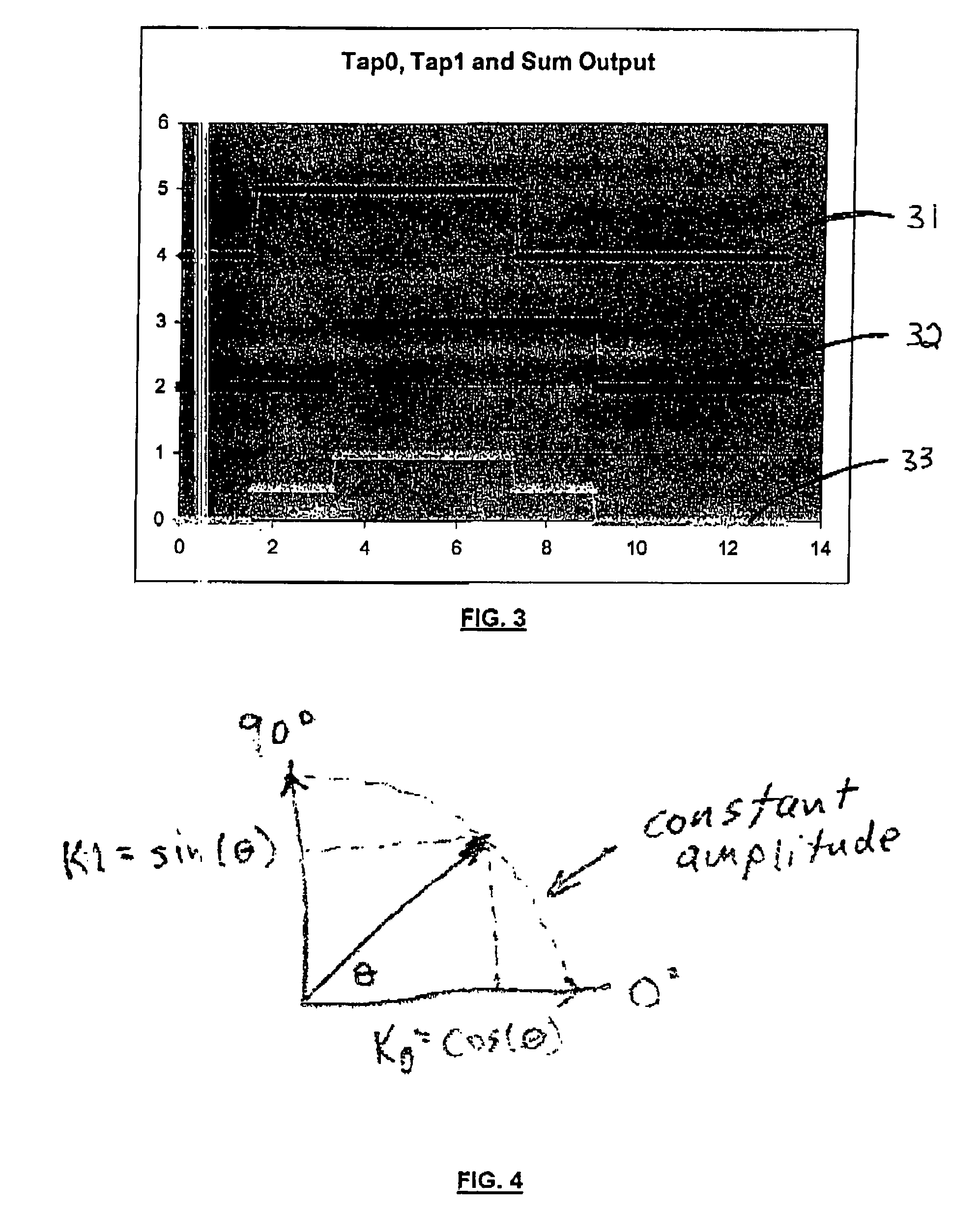
[0022] The present invention is a method and apparatus used to create variable delay for input trigger edges. The input is a signal containing trigger edges and the output is a like-signal containing nearly similar trigger edges that are delayed by a variable amount of delay. The variable nature of the output delay is controlled by a control input that varies the output delay from Tmin to Tmax where Tmax−Tmin=Δt is the delay range of the variable delay device. The control input in this invention controls the mu...


PUM


Abstract

Disclosed herein is a method and apparatus used to create variable delay output from a high-speed trigger input signal. A variable delay generation circuit includes a preconditioning circuit, operative to provide a preconditioned signal in response to an input signal. At least one delay tap path is coupled to the preconditioned signal, and is operative to provide a delayed version of the preconditioned signal. The delay path includes a delay element and a scaling circuit. A summing circuit is coupled to the at least one delay tap path and preconditioned signal, and is operative to provide an output signal exhibiting variable delay characteristics in response to the preconditioned signal and the delayed version of the preconditioned signal. The delayed version of the preconditioned signal may be provided by an elongated signal trace between the preconditioning circuit and the delay tap path. Through the combination of summing delayed and scaled versions of the input signal and the preconditioning of the input signal to have required rise / fall times and shapes, high-frequency variable delay is implemented that provides for fast, stable settings with consistent delay range and resolution.

Description

BACKGROUND OF THE INVENTION [0001] 1. Field of the Invention [0002] This invention generally relates to test and measurement systems that need precise, high-speed variable delay of triggering edges. [0003] 2. Description of the Related Art [0004] In recent years, the performance of high-speed communication facilities and devices have risen to a point that the ability to accurately achieve high-quality delay in a signal or trigger at very high frequencies can dramatically impact the type of test performed as well as the test time for such facilities and devices. Conventional mechanisms for achieving variable delay have had one or more drawbacks in areas of frequency capability, resolution of delay, linearity of delay, monotonicity of delay, speed of setting delay, reliability, temperature dependence of delay, and range of delay. [0005] Past delay devices have included mechanical trombone-type variable delay structures, where a stepper motor is used to physically elongate a coaxial co...

Claims


Application Information

Patent Timeline
Patent Type & Authority Applications(United States)
IPC IPC(8): H03H11/26H03K5/13
CPCH03K5/13H03H11/265
Inventor POSKATCHEEV, ANDREI
Owner SYNTHESYS
Why Eureka
Try Eureka