
Optical True Delay Method and System Based on Dispersion and Spectrum Processing

An optical true delay and dispersion technology, applied in the field of optical signal processing, can solve the problems of increasing the delay step, limited delay range, limited transmission bandwidth, etc., to improve the accuracy and expand the delay range. Effect

Active Publication Date: 2015-12-23
TSINGHUA UNIV
View PDF3 Cites 0 Cited by
  • Summary
  • Abstract
  • Description
  • Claims
  • Application Information

AI Technical Summary

Problems solved by technology

It can be seen that in the case where the tuning range of the laser is limited, to achieve a large delay, the only way to increase the dispersion of the dispersion device
And this will inevitably increase the delay step and reduce the continuity of delay tuning
[0004] There is a serious problem in the delay technology using dispersion: the microwave power fading caused by dispersion
[0013] Existing technical solutions cannot take into account both delay range and delay fineness
figure 1 The technical solution in can achieve a wide range of delay, but the step is often large, and the transmission bandwidth is also limited
and figure 2 The technical solution in achieves fine tuning of the delay, but the range of delay is limited

Method used


Image

  • Optical True Delay Method and System Based on Dispersion and Spectrum Processing
  • Optical True Delay Method and System Based on Dispersion and Spectrum Processing
  • Optical True Delay Method and System Based on Dispersion and Spectrum Processing

Examples


Embodiment Construction

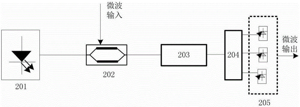
[0054] Embodiments of the present invention are described in detail below, and examples of the embodiments are shown in the drawings, wherein the same or similar reference numerals denote the same or similar elements or elements having the same or similar functions throughout. The embodiments described below by referring to the figures are exemplary only for explaining the present invention and should not be construed as limiting the present invention.

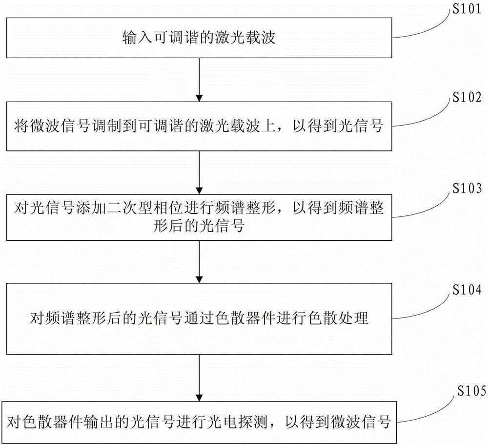
[0055] image 3 It is a flowchart of an optical true time delay method based on dispersion and spectrum processing according to an embodiment of the present invention. Such as image 3 As shown, the optical true delay method based on dispersion and spectrum processing according to an embodiment of the present invention includes the following steps:

[0056] Step 101, input a tunable laser carrier.

[0057] Specifically, a tunable laser carrier is generated by a tunable laser

[0058] In step 102, the microwave signal is mo...


PUM


Abstract

The invention provides an optical true time delay method and system based on dispersion and frequency spectrum processing. The optical true time delay method comprises the following steps: a tunable laser carrier is input; a microwave signal is modulated onto the tunable laser carrier to obtain an optical signal; a quadratic-form phase is added to the optical signal for frequency spectrum reshaping so as to obtain the optical signal after the frequency spectrum reshaping; the optical signal after the frequency spectrum reshaping is subjected to the dispersion processing through a dispersion element; the optical signal output by the dispersion element is subjected to photoelectric detection to obtain a microwave signal, wherein wide-range time delay is realized through adjustment of the frequency of the laser carrier, and the time delay range is within 0-1,717ps; fine adjustment of time delay is realized through control over the quadratic-form phase, and the stepping rate of the time delay is 0.67ps. According to the optical true time delay method, the frequency spectrum reshaping is realized in the mode that the quadratic-form phase is added to an optical frequency spectrum, so that fine tuning of the time delay is realized, and the accuracy is improved. Through laser wavelength tuning and the dispersion element, the time delay range of the microwave signal is expanded.

Description

technical field [0001] The invention relates to the technical field of optical signal processing, in particular to an optical true delay method and system based on dispersion and spectrum processing. Background technique [0002] Optical true time delay technology (optical true time delay, OTTD) refers to the use of photonics methods to achieve controllable delay of microwave signals. It has broad application prospects in phased array technology, signal processing technology, and optical network cache. Compared with the electrical method, it has the advantages of low loss, large bandwidth, small size, and anti-electromagnetic interference. The time required for the optical signal to pass through the waveguide can be expressed as: τ=n(ω)l / c, where τ is the delay of the optical signal, n(ω) is the refractive index, and l is the length of the waveguide. Based on the above formula, there are mainly the following methods to achieve optical true delay: (1) Switching optical fibe...

Claims


Application Information

Patent Timeline
Patent Type & Authority Patents(China)
IPC IPC(8): H04B10/2513
Inventor 郑小平宋云龙李尚远张汉一周炳琨
Owner TSINGHUA UNIV
Learn More