
A Pneumatic Delay Reversing Valve

A reversing valve and valve core technology, which is used in fluid pressure actuating devices, servo motor components, mechanical equipment, etc. Due to the complex structure of the valve, the effects of light weight, increased delay range and small size are achieved.

Active Publication Date: 2018-02-16
湖州通元石料有限公司
View PDF6 Cites 0 Cited by
  • Summary
  • Abstract
  • Description
  • Claims
  • Application Information

AI Technical Summary

Problems solved by technology

At present, the commonly used control methods of the delay reversing valve are as follows: electromagnetic control, air pressure control, manual control and mechanical control. These control methods currently have certain technical problems: the delay reversing valve of electromagnetic control An external power supply is required; the manual control delay reversing valve is too low in automation, it is difficult to accurately control the delay time, and the frequency of use is low, and the action speed is slow; the mechanical control delay reversing valve is usually too complicated in structure and reliable. The performance is not high; and the most widely used air pressure control delay reversing valve has the defect that the delay adjustable range is small, generally within one minute.

Method used


Image

  • A Pneumatic Delay Reversing Valve
  • A Pneumatic Delay Reversing Valve

Examples


Embodiment

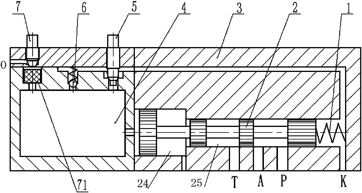
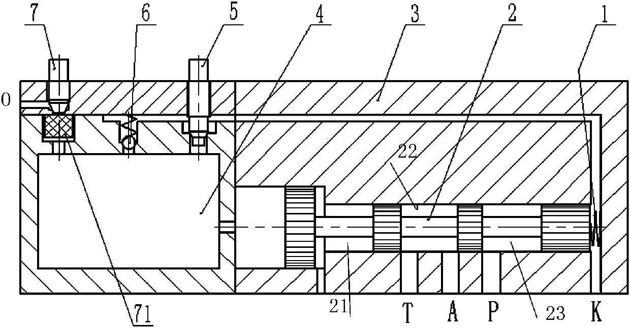
[0023] like Figure 1-2 The pneumatic time-delay reversing valve shown is composed of spring 1, spool 2, valve body 3, air chamber 4, throttle valve 5, check valve 6, miniature throttle valve 7 and composed of elastic columns 71; the left end of the valve body 3 is provided with an air chamber 4, and the right end is provided with a stepped valve core cavity, the valve core 2 and spring 1 are coaxially placed in the valve core cavity, and the spring 1 is located At the right end of the spool, the spool 2 is slidingly fitted with the spool chamber, and a through hole for communicating with the air chamber 4 and the spool chamber is provided between the air chamber 4 and the spool chamber; in the valve body 1. Throttle valve 5, one-way valve 6 and micro-throttle valve 7 are arranged on the upper end, and the air chamber 4 communicates with the vent hole at the bottom of said throttle valve 5, one-way valve 6 and micro-throttle valve 7 respectively , the flow rate of the micro-t...


PUM


Abstract

The invention discloses a pneumatic delay reversing valve. The pneumatic delay reversing valve comprises a valve body, a valve element and a spring. An air containing chamber is arranged at one end of the valve body, and a stepped valve element cavity is formed in the other end of the valve body. The valve element and the spring are coaxially arranged in the valve element cavity. A through hole is formed between the air containing chamber and the valve element cavity. A throttling valve, a check valve and a miniature throttling valve are arranged at the upper end of the valve body and further communicate with the air containing chamber. An outlet of the miniature throttling valve is connected with a valve body exhaust end opening. A control end opening, an air inlet end opening, an air outlet end opening and an unloading end opening are sequentially formed in the lower portion of the valve element cavity. The valve element is a stepped cylinder with at least two grooves formed in the radial direction. In the initiating / starting process, the air outlet end opening and the air inlet end opening are located in the same groove. In the closing process, the air outlet end opening and the air inlet end opening are located in the adjacent grooves. The pneumatic delay reversing valve has the advantages that the structure is simple and compact, the weight is low, performance is good, the process is simple and easy to implement, an existing pneumatic delay reversing valve can be refitted conveniently, and the technical requirements of products produced can be met.

Description

technical field [0001] The invention relates to a valve, in particular to a pneumatic time-delay reversing valve. Background technique [0002] The time-delay reversing valve is mainly used to control the reversing frequency and on-off time ratio of gas. At present, the commonly used control methods of the delay reversing valve are as follows: electromagnetic control, air pressure control, manual control and mechanical control. These control methods currently have certain technical problems: the delay reversing valve of electromagnetic control An external power supply is required; the manual control delay reversing valve is too low in automation, it is difficult to accurately control the delay time, and the frequency of use is low, and the action speed is slow; the mechanical control delay reversing valve is usually too complicated in structure and reliable. The performance is not high; and the most widely used air pressure control delay reversing valve has the defect that ...

Claims


Application Information

Patent Timeline
Patent Type & Authority Patents(China)
IPC IPC(8): F15B13/02
CPCF15B13/021
Inventor 李春庄王拥军李研
Owner 湖州通元石料有限公司
Learn More