
Modular meter configuration and methodology

a technology of modular meters and meter configurations, applied in the direction of dynamo-electric motor meters, instruments, measurement devices, etc., can solve the problems of generating considerable industry problems, limiting the basic mechanical form of registers, and difficult to implement relatively newer technologies, etc., to improve design stability, improve simplicity, and improve cost efficiency

Inactive Publication Date: 2005-07-28
ITRON
View PDF67 Cites 25 Cited by
  • Summary
  • Abstract
  • Description
  • Claims
  • Application Information

AI Technical Summary

Benefits of technology

[0026] Yet another general object of the present invention is to provide improved meter configurations and corresponding methodologies which advantageously permit use of separate printed circuit boards, one for standard or basic features and another for customized, more advanced functions. In accordance with such aspect of the present invention, it is a more particular object to permit customization of the higher level of functionality (or “personality”) of meter configurations in accordance with the invention. Such advantages further result in improved delivery of manufactured devices to utility company customers, both with respect to cost efficiency and timeliness.
[0040] Yet another construction comprising an improved meter configuration and corresponding methodology in accordance with the subject invention makes use of tapered mounting posts and various snap fit features for providing a stable meter construction without requiring screws or other individual fastener elements.

Problems solved by technology

The foregoing basic mechanical form of register is typically limited in its mode of output, so that only a very basic or lower level metrology function is achieved.
Implementing incremental changes in technology, such as retrofittable features, or changes to basic components making various components not interchangeable with other configurations already in the field, can generate considerable industry problems.
From the perspectives of manufacturers in the industry, it can be difficult to implement relatively newer technologies., even after they have clearly been proven, simply due to the large scale inertia of the total system being potentially affected.
While various aspects and alternative features are known in the metering field, no one design has emerged generally integrating customer options based on modular meter configurations and corresponding methodologies.

Method used


Image

  • Modular meter configuration and methodology
  • Modular meter configuration and methodology
  • Modular meter configuration and methodology

Examples


first embodiment

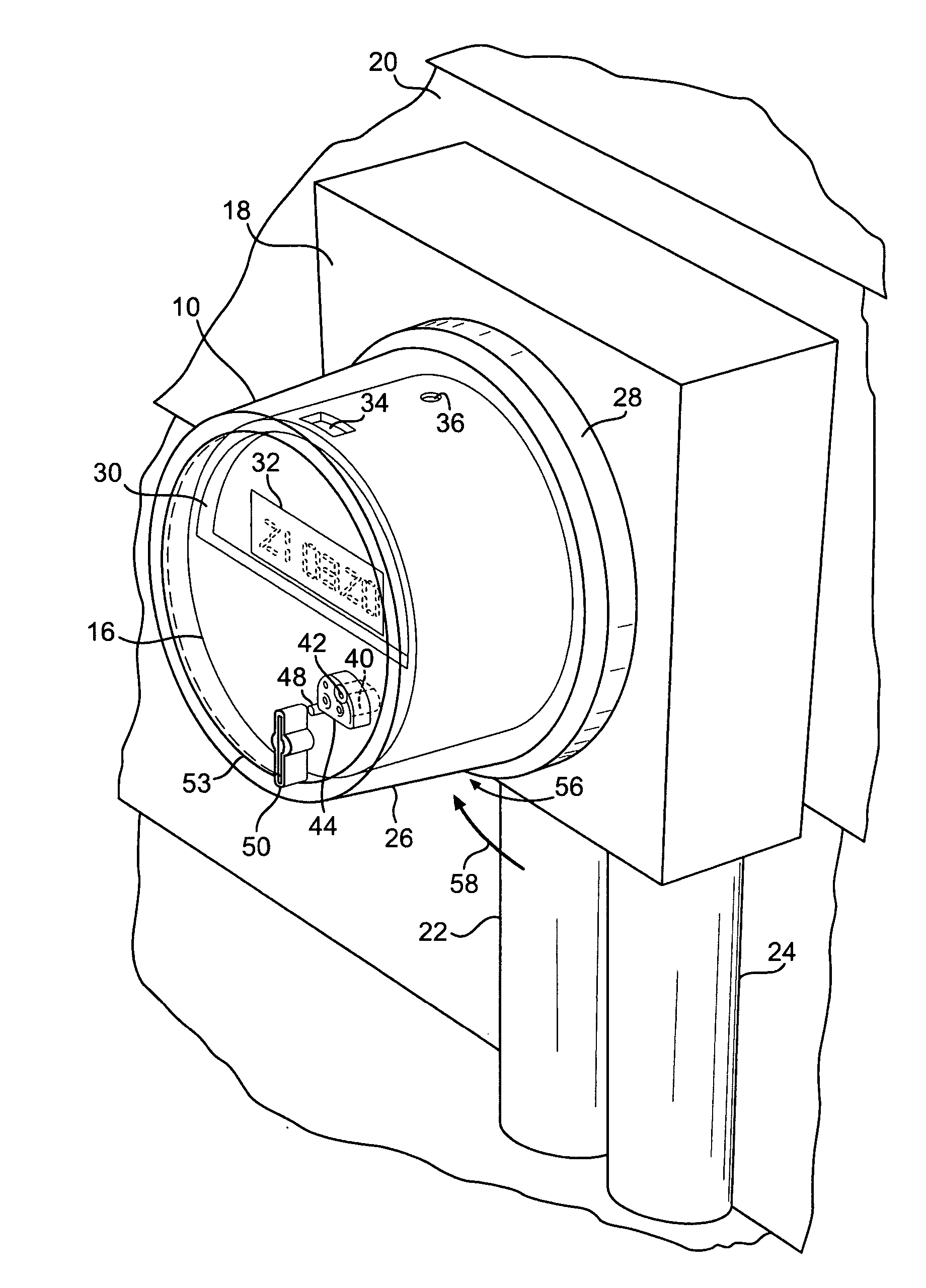
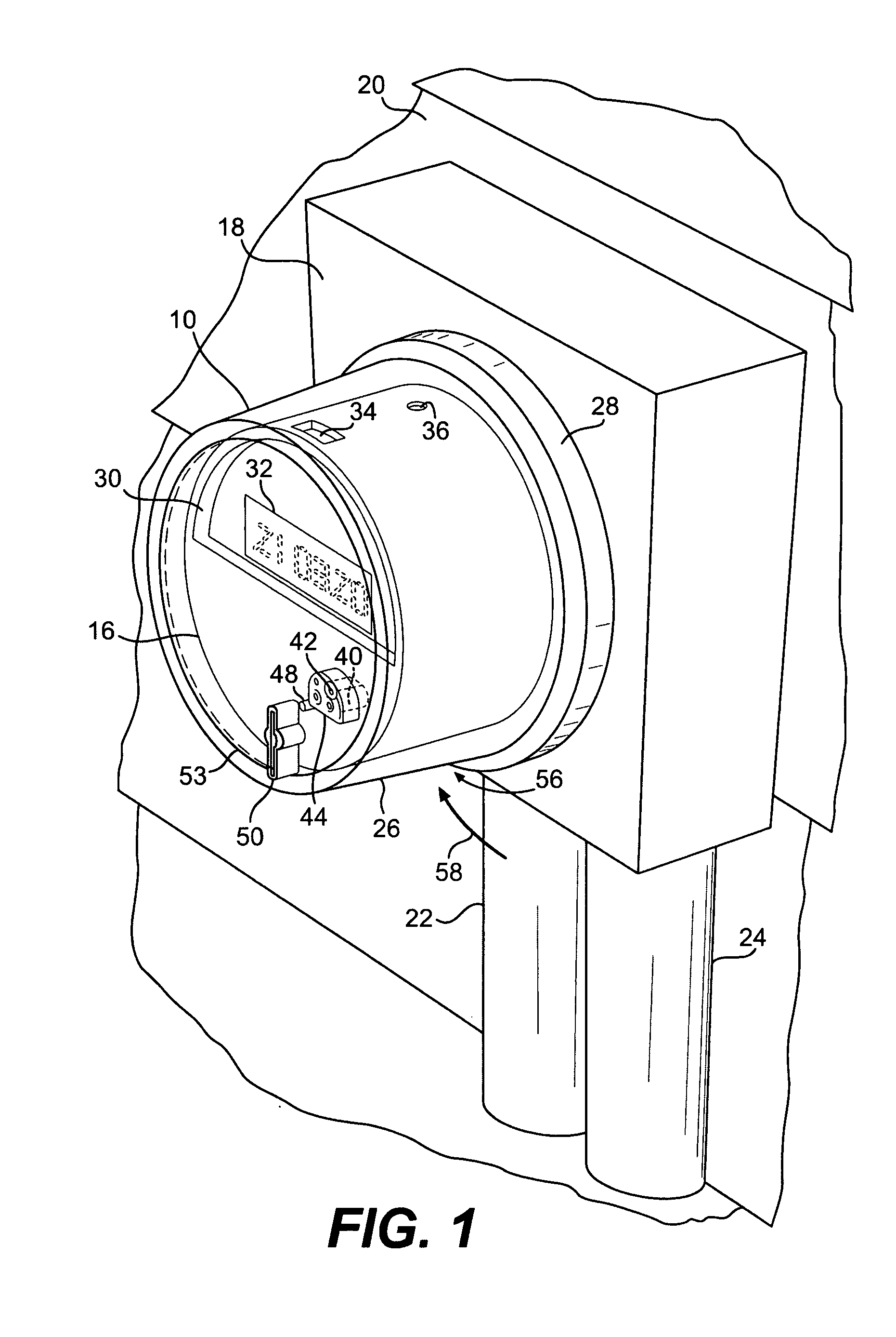
[0117]FIG. 7 provides an identical illustration to FIG. 6, with the addition of various coil assembly features and features specifically for the above-referenced first embodiment of the subject invention, involving two integrated circuit boards and corresponding solid state circuitry and an electronic register for data output.

[0118] More particularly, inclusion of full view illustrations in FIGS. 7 through 9 (rather than cross sections) of core elements 124 and 126, laminated core 128 and core cover (or support) 130 results in blocked viewing of cantilevered connectors 154 and 156.

[0119] The additional elements illustrated in present FIG. 7 relative to FIG. 6 so as to illustrate a more complete first embodiment of device 12 in accordance with the subject invention generally include the following. First, the basic function or first circuit board 140 is shown, as used in combination with the customized feature or second circuit board generally 162.

[0120] As shown in FIG. 7, circuit ...

second embodiment

[0124] More particularly, the second embodiment device 234 of FIG. 8 may include a mechanical wheel assembly, with numbers mounted on a wheel mounting to fingers or extensions of the support chassis 170. More specifically, exemplary wheel generally 238 represents a plurality of such wheels laterally disposed adjacent one another for providing mechanical register output.

[0125] As well understood by those of ordinary skill in the art without additional details, such plurality of wheels 238 may be supported within an integral structure, such as having a rear wall generally 240 and front wall 242 thereof. A pair of upper curved fingers generally 244 (only one shown due to the cross sectional nature of FIG. 8) capture an upper edge of rear or back wall generally 240 of the integral cyclometer mechanical register assembly generally 246. Such curved fingers 244 are preferably integrally formed with chassis 170, which also provides a pair of lower capture elements generally 248 (only one sh...

embodiment 236

[0127] The mechanical register assembly device embodiment 236 of present FIG. 9 is similar to that of present FIG. 8, but has its own form of mechanical register assembly generally 250. Such mechanical register 250 may comprise a clock register type of assembly, well known to those of ordinary skill in the art. Such assembly 250 may preferably comprise an integral arrangement having rear and front walls 252 and 254, respectively. As illustrated, the rear wall may be captured or secured by chassis 170, including an upper pair of elements 208 thereof, and intermediate pairs of fingers 204 thereof, cooperating with both pairs of stop elements 206. Exemplary support elements 256 and 258 represent mechanical support between rear wall 252 and front wall 254 of mechanical register assembly 250.

[0128] As understood by those of ordinary skill in the art, a plurality of relatively smaller dial elements generally 260 are driven clock-style in respective scaled relationships via a series of gea...


PUM


Abstract

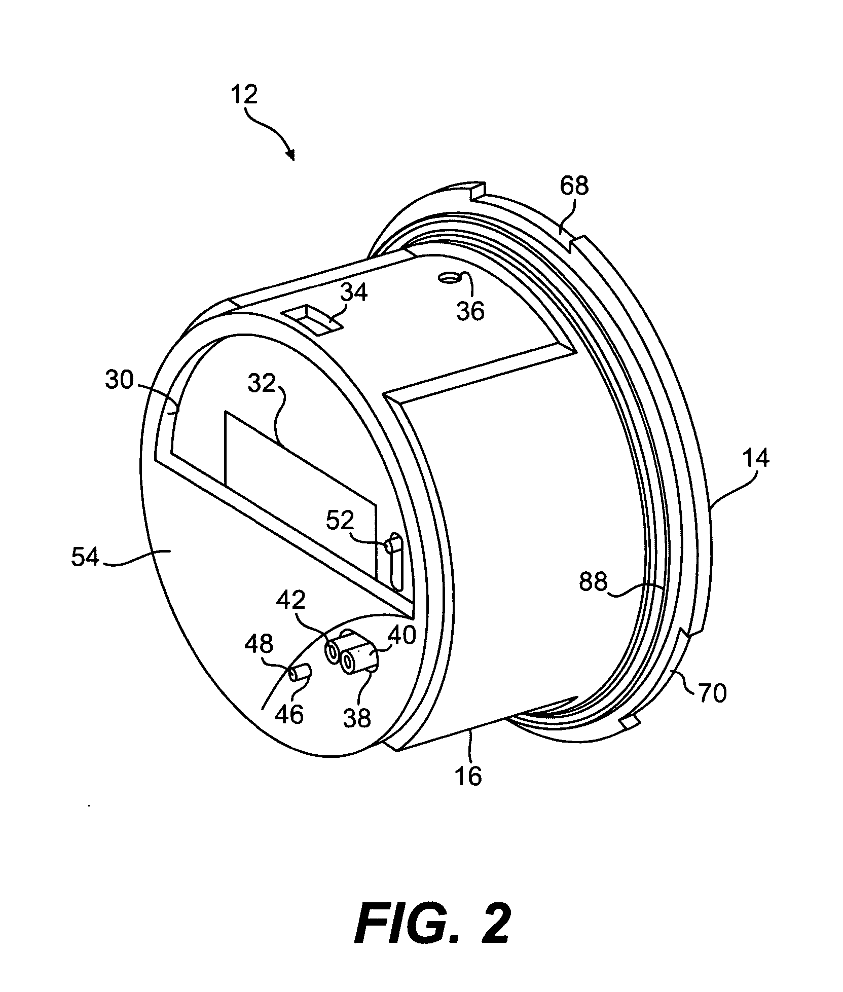
A modular electricity meter configuration and corresponding methodology permits use of certain common components in combination with either a variety of mechanical displays or electronic displays. In electricity meter arrangements making use of printed circuit board or solid state technology, at least two separate electronics boards may be provided. One may constitute a standard board for basic metrology functions while the other may comprise selected implementation of various higher level functions for creating a custom design electricity meter to meet customer requirements. Different customers may be provided with differently outfitted meters by corresponding customization of the higher level function board. A unitary power supply may be provided for both boards through a fixed connector. A common baseplate includes a circuitry link through a nonremovable plug or clip for alternatively providing a tamper proof embodiment or one with exposed terminals for permitting customer testing. Physical stability and strength is provided by using tapered mounting posts and integrated snap fit arrangements without requiring any screws for assembly. A light pipe provides external output through an innercover to indicate correct meter operation. Meter data and other metered information may be output through different configurations optionally involving hardwired output, RF links, pulse outputs, and telephone connections via modem or wireless.

Description

PRIORITY CLAIMS [0001] This application is a continuation of U.S. patent application Ser. No. 09 / 450,890 filed Nov. 29, 1999 entitled “MODULAR METER CONFIGURATION AND METHODOLOGY”, which, in turn, claims the benefit of U.S. Provisional Application No. 60 / 110,457, filed Dec. 1, 1998.BACKGROUND OF THE INVENTION [0002] The present invention generally concerns improved configurations and corresponding methodologies for modular meters and related features, and more particularly concerns integrated production of electricity meters capable of assuming a wide variety of optional and alternative features in respective embodiments based on certain common, base features. The subject invention concerns both apparatuses and methodologies in such areas, including in some instances the use of practical computer software applications involving an algorithmic approach to producing a useful, concrete and tangible result, i.e., namely, specific basic and selected higher level metrology functions. [000...

Claims


Application Information

Patent Timeline
Patent Type & Authority Applications(United States)
IPC IPC(8): G01R11/02G01R11/04G01R11/24G01R22/00
CPCG01R22/066G01R22/065G01R21/08G02B27/0994
Inventor MAKINSON, DAVID N.PHILPOT, LUDLOW
Owner ITRON
Learn More