
Gassing-free exposure mask

Inactive Publication Date: 2005-07-21
POLARIS INNOVATIONS
View PDF4 Cites 0 Cited by
  • Summary
  • Abstract
  • Description
  • Claims
  • Application Information

AI Technical Summary

Benefits of technology

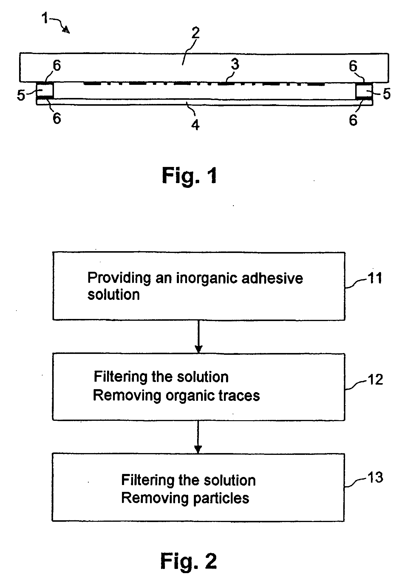
[0014] The reticle, the frame and the pellicle of the exposure mask preferably inclues quartz glass and are connected with an inorganic adhesive of the waterglass type, which includes at least the elements silicon, oxygen and an alkali metal. Such an exposure mask built up completely from inorganic quartz glass components is, as explained above, particularly suitable for an exposure wavelength of 157 nm. Since the components are comprised of the same material, no problems caused by different thermal expansions arise. The adhesive of the waterglass type achieves good adhesive strengths on the quartz glass components and may be produced simply and economically. Furthermore, for chemical reasons, gassing out is ruled out completely in the case of an adhesive of this type.
[0017] In still another embodiment of the invention, there is a method a for producing an inorganic adhesive which is suitable as an adhesive means for connecting a reticle, a frame and a pellicle of an exposure mask. In this case, in a first method step, an inorganic adhesive solution is provided and, in a second method step, this solution is filtered with a first filtering device in order to remove organic traces which can cause gassing out. Then, in a third method step, the solution is filtered with a second filtering device in order to remove particles. With the aid of this method, which in particular can even be carried out with commercially available adhesive solutions, a gassing-free inorganic adhesive can be produced simply and with little expenditure.
[0018] In the embodiment which is preferred for practical use, the filtering of the solution with a first filtering device is carried out by shaking the solution with active carbon, by which means organic components of the solution can be removed very reliably.
[0020] After the second method step, additional drying of the adhesive is preferably carried out, in order to minimize the components which emerge during a drying process and which can also emerge in the region enclosed by reticle, frame and pellicle.

Problems solved by technology

The resolving power of an exposure method, and therefore the achievable size of the semiconductor structures, is limited by the wavelength of the radiation used.
However, in the case of these organic compounds, there is the problem that they tend to gas out and, as a result, in spite of the sealing achieved with the aid of the frame and the pellicle, particles can be deposited on the lithographic structure on the reticle.
In addition, it is disadvantageous that these radiation-induced chemical reactions increase, the smaller the exposure wavelength used is, since the radiation energy increases as the wavelength is reduced.
In parallel with this, the mask structures are becoming smaller and smaller in the course of the miniaturization of the semiconductor structures and, as a result, are becoming more and more susceptible to deposits on the lithographic structure.

Method used


Image

  • Gassing-free exposure mask
  • Gassing-free exposure mask
  • Gassing-free exposure mask

Examples


first embodiment

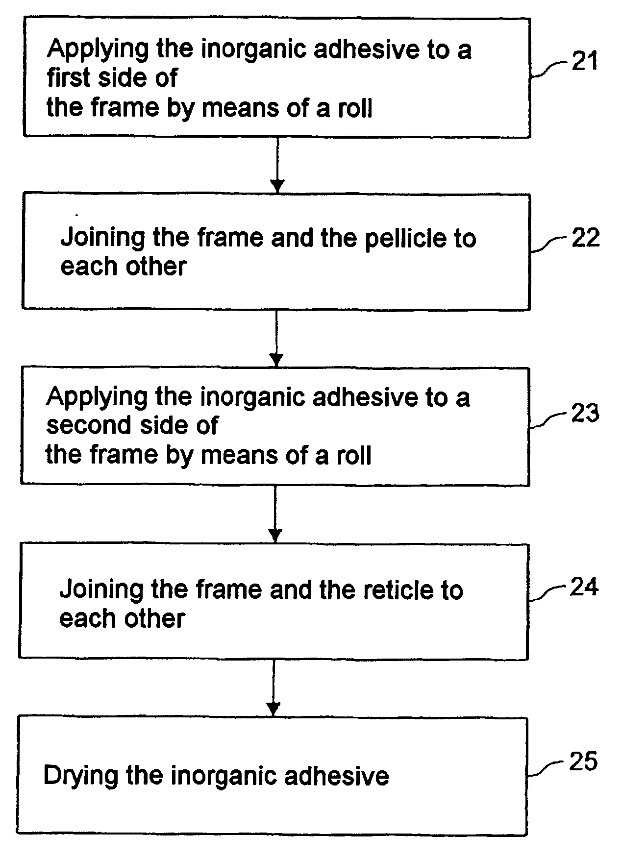
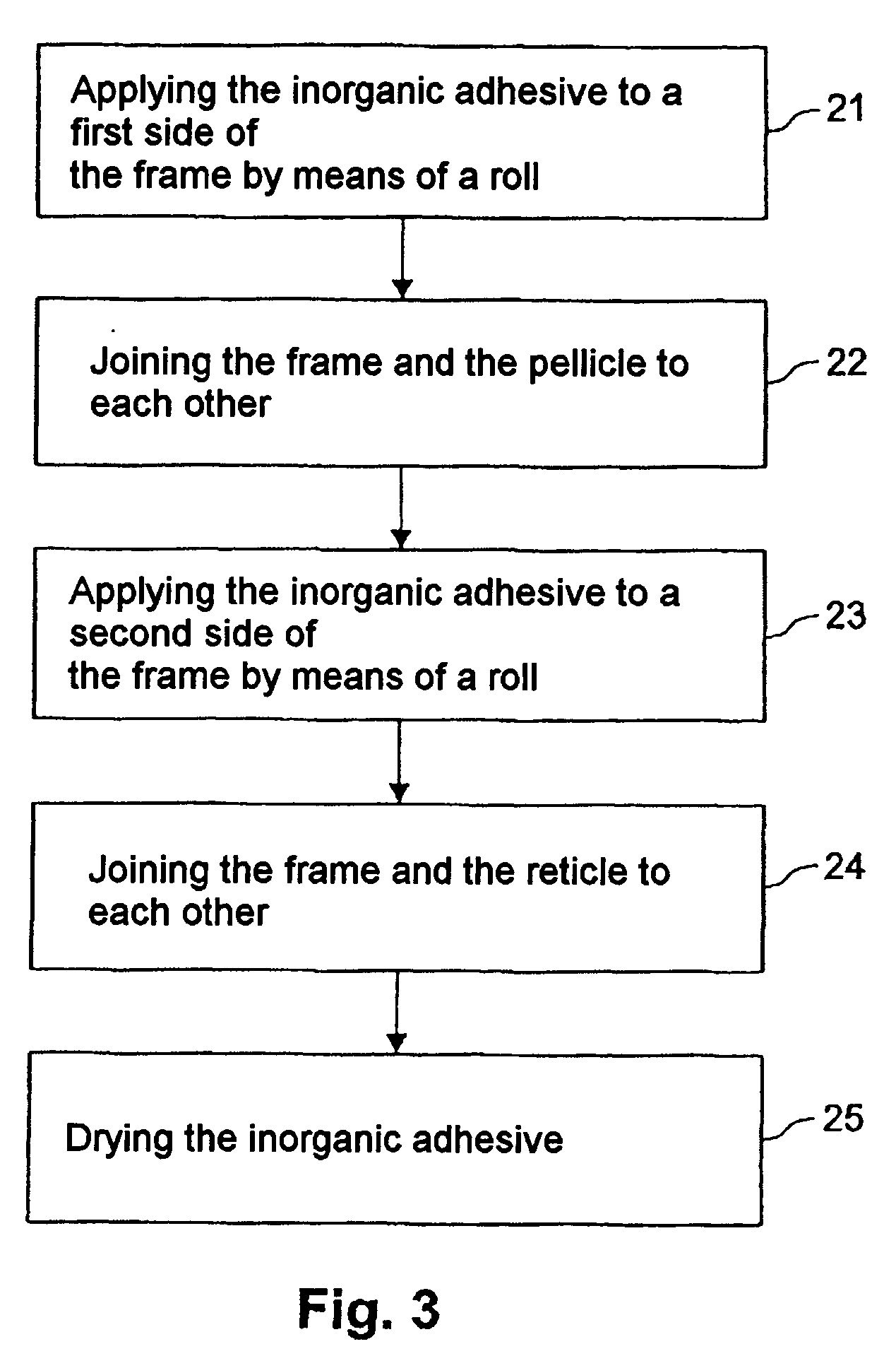
[0035]FIG. 3 shows a flow chart of a method according to the invention for producing the exposure mask 1 illustrated in FIG. 1. In this case, in a first method step 21, the inorganic adhesive is applied to a first side of the frame with the aid of a roll. One important precondition is that the areas to which the inorganic adhesive is applied are clean and have previously been degreased or cleaned as required, in order to achieve a good adhesive strength of the adhesive. The roll used is preferably comprised of cross-linked polyvinyl alcohol, which permits the adhesive to be applied easily to a surface as a thin layer. After that, in a second method step 22, the corresponding sides of the frame and of the pellicle to be bonded are joined to each other.

[0036] In a third method step 23, the inorganic adhesive is applied to a second side of the frame and then, in a fourth method step 24, the corresponding sides of the frame and of the reticle to be bonded are joined to each other.

[0037...

second embodiment

[0038] Alternatively, a method according to the invention for producing the exposure mask illustrated in FIG. 1 can be carried out, of which the flow chart is illustrated in FIG. 4. In this case, in a first method step 31, the inorganic adhesive is applied to a first side of the frame with a metering cannula and then, in a second method step 32, the corresponding surfaces of the frame and of the pellicle to be bonded are joined to each other. The inorganic adhesive may be applied more precisely to the surface with a metering cannula as opposed to a roll.

[0039] Following that, in a third method step 33, the inorganic adhesive is dried before, in a fourth method step 34, the adhesive is applied with the metering cannula to a second side of the frame, the corresponding sides of the frame and of the reticle to be bonded are joined to each other in a fifth method step 35, and the adhesive is again dried in a sixth method step 36.

[0040] The additional drying of the adhesive in the third ...


PUM

PropertyMeasurementUnit
Temperatureaaaaaaaaaa
Lengthaaaaaaaaaa
Lengthaaaaaaaaaa

Abstract

The present invention relates to an exposure mask for structuring a photoresist layer on a substrate wafer, in which an inorganic adhesive is used as an adhesive device for connecting a reticle having a lithographic structure, a frame and a pellicle. For chemical reasons, an adhesive of this type has no tendency or a considerably lower tendency to gassing out than an organic adhesive used in conventional exposure masks, so that the risk of particles which are deposited on the lithographic structure and which can cause projection errors during an exposure process is largely ruled out. The invention relates further to a method of producing such an inorganic adhesive and also a method of producing an exposure mask with the aid of such an inorganic adhesive.

Description

CLAIM FOR PRIORITY [0001] This application claims the benefit of priority to German Application No. 103 21 278.7-51, filed in the German language on May 13, 2003, the contents of which are hereby incorporated by reference. TEHCNICAL FIELD OF THE INVENTION [0002] The present invention relates to an exposure mask, and in particular, to an exposure mask in which an inorganic adhesive is used as an adhesive device for connecting a reticle, a frame and a pellicle. The invention relates further to a method for producing such an inorganic adhesive and a method for producing an exposure mask with the aid of such an inorganic adhesive. BACKGROUND OF THE INVENTION [0003] In order to implement highly integrated electrical circuits with small structure dimensions, lithographic structuring methods are normally used. In this case, a radiation-sensitive photoresist layer is applied to the surface of a semiconductor substrate wafer to be structured and is exposed through an exposure mask with the a...

Claims


Application Information

Patent Timeline
IPC IPC(8): A47G1/12B44F1/00C09J1/00G03B27/62G03F1/64G03F9/00
CPCG03F1/64
Inventor GEYER, STEFAN
Owner POLARIS INNOVATIONS
Learn More