
Radio communication device and control data retreiving method

a radio communication device and control data technology, applied in the field of radio communication devices, can solve the problems of difficult to retrieve the base station, all fixed frequencies which are selected might be subject to interference, and the return to the standby state is delayed, so as to reduce the consumed current of the retrieval

Inactive Publication Date: 2005-07-21
PANASONIC CORP
View PDF6 Cites 46 Cited by
  • Summary
  • Abstract
  • Description
  • Claims
  • Application Information

AI Technical Summary

Benefits of technology

[0014] It is an object of the invention to provide a radio communication device capable of reducing the consumed current of a retrieving operation in an environment in which control data cannot be received from a base station, and a control data retrieving method for reducing the consumed current of the retrieving operation in the environment in which the control data cannot be received from the base station.
[0016] Consequently, it is possible to obtain the radio communication device capable of reducing the consumed current of a retrieving operation when it is put in the environment in which the control data transmitted from the base station cannot be received, that is, it is put on the outside of the sphere of the base station, and quickly receiving the control data from the base station when the base station is changed into a receivable state, and returning to a standby state immediately and rapidly.
[0017] In a radio communication device for carrying out a communication by using a frequency hopping method, moreover, when an intermittent receiving operation is to be carried out in order to capture the control data transmitted from the base station during a standby, the radio portion is controlled to start a receiving operation of the radio portion in order to receive any of frequencies used in the transmission of the control data of the base station and to stop the receiving operation if the control data cannot be received for a predetermined receiving period, and to then restart the receiving operation after a predetermined halt period passes, and is controlled to switch a receiving period of the intermittent receiving operation to be short and to decrease the number of frequencies to be selected for the receiving period if the control data transmitted from the base station cannot be captured for a predetermined period.

Problems solved by technology

Thus, there is a problem in that a return to the standby state is delayed.
In the environment in which a plurality of radio LANs is present, however, there is a possibility that all of the fixed frequencies which are selected might be subjected to an interference.
Therefore, there is a problem in that it is hard to retrieve the base station in some cases.
In the case in which the number of frequencies to be received is increased in order to lessen the danger of a receiving error which is caused by the interference, moreover, there is a problem in that the consumed current is increased in a situation in which a signal sent from the base station cannot be received even if a disturbance is not caused by the interference.

Method used


Image

  • Radio communication device and control data retreiving method
  • Radio communication device and control data retreiving method
  • Radio communication device and control data retreiving method

Examples


first embodiment

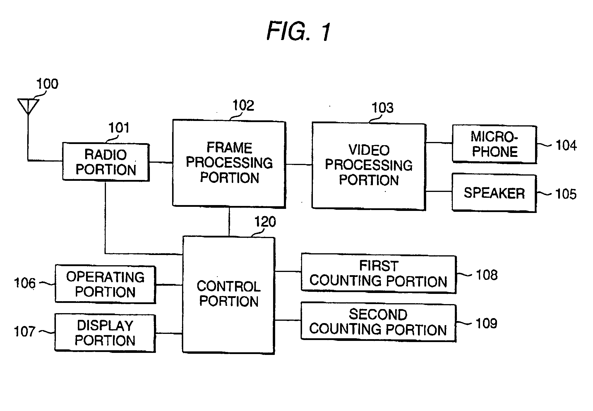
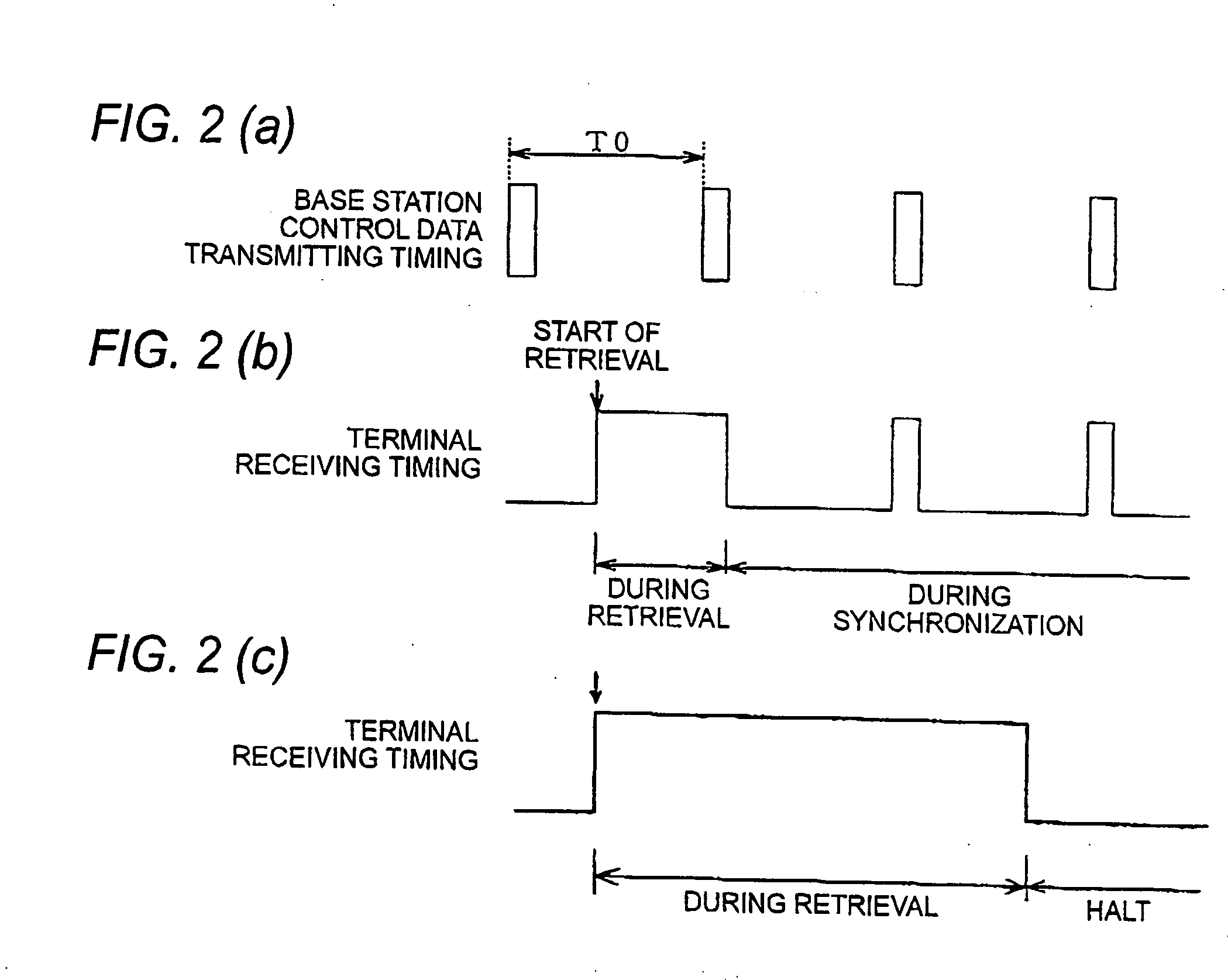
[0029]FIG. 1 is a block diagram showing a radio communication device according to a first embodiment of the invention, FIG. 2(a) is a timing chart showing the transmitting timing of the control data of a base station, FIG. 2(b) is a timing chart showing a receiving timing in the radio communication device (terminal), FIG. 3 is a timing chart showing a retrieving timing in the radio communication device, and FIG. 4 is a flowchart showing the operation of the radio communication device in FIG. 1.

[0030] In FIG. 1, 100 denotes an antenna for inputting / outputting a radio signal to / from a base station (not shown), 101 denotes a radio portion for generating a radio signal obtained by modulating transmission data so as to be transmitted and demodulating the radio signal which is received, 102 denotes a frame processing portion for generating a data column to be transmitted in one slot of TDMA by adding bit synchronization data, frame synchronization data or an error detection code to the t...

second embodiment

[0064]FIG. 5 is a block diagram showing a radio communication device according to a second embodiment of the invention, FIGS. 6(a), (b) and (c) are timing charts showing a retrieving timing, and FIG. 7 is a flowchart showing the operation of the radio communication device in FIG. 5.

[0065] In FIG. 5, since an antenna 100, a radio portion 101, a frame processing portion 102, a voice processing portion 103, a microphone 104, a speaker 105, an operating portion 106 and a display portion 107 are the same as those in FIG. 1, they have the same reference numerals and description thereof will be omitted. 110 denotes a counting portion for counting a retrieval time and a stop time during the retrieval of a base station in the retrieval of the base station, and 130 denotes a control portion for controlling the whole device. An operation to be carried out during a communication in the radio communication device in FIG. 5 and an operation in which an operation for receiving the control channel...

third embodiment

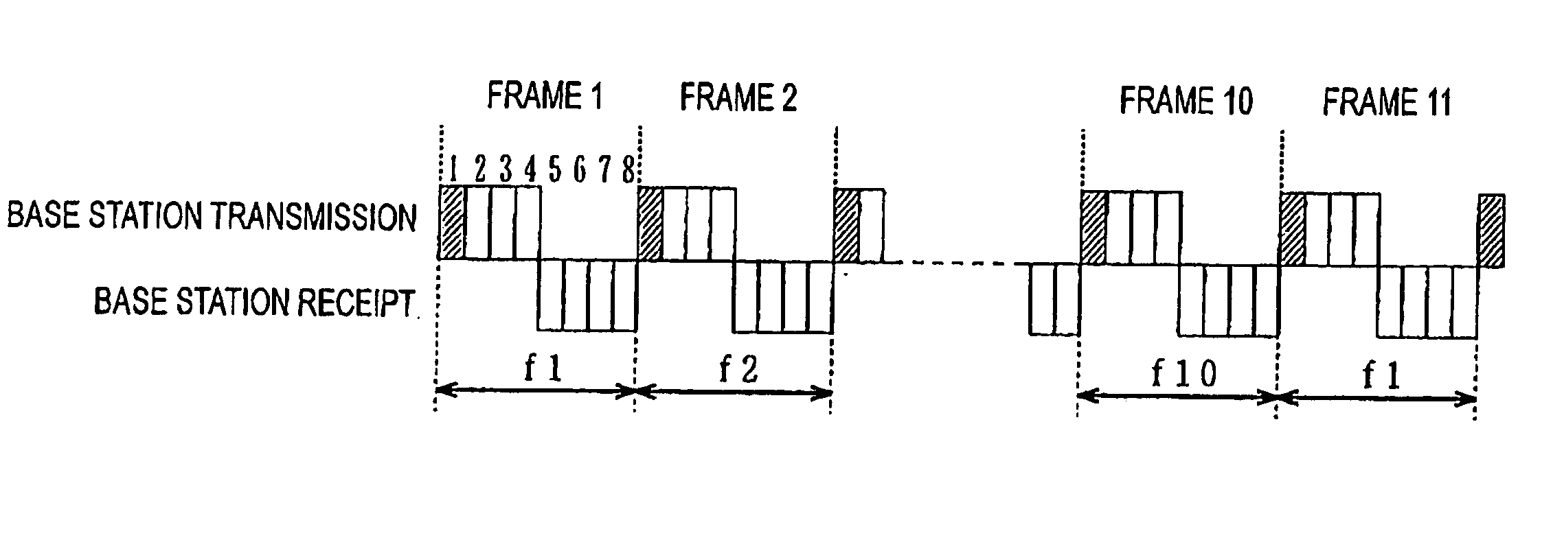
[0084]FIG. 8 is a block diagram showing a radio communication device according to a third embodiment of the invention and FIG. 9 is a timing chart showing a TDMA frame and slot and frequency hopping which are used in a communication between the radio communication device in FIG. 8 and a base station. FIG. 10(a) is a timing chart showing the transmitting timing of control data from the base station, FIG. 10(b) is a timing chart showing a receiving timing in the radio communication device, FIG. 11 is a timing chart showing an operation in which the radio communication device retrieves the transmitting signal of the control data of the base station and cannot receive the control data of the base station but repeats a retrieval and a stop, and FIG. 12 is a flowchart showing an operation in which the radio communication device retrieves the transmitting signal of the control data of the base station and cannot receive the control data of the base station but repeats the retrieval and the...


PUM


Abstract

The invention provides a radio communication device for carrying out a time division communication, thereby communicating with a base station for transmitting control data, wherein when an intermittent receiving operation is to be performed in order to capture the control data transmitted from the base station during a standby, the receiving operation of the radio portion is started to periodically receive the control data of the base station, the receiving operation is stopped if the control data cannot be received for a predetermined receipt period, the receiving operation is then restarted repetitively after a predetermined halt period passes, and a receiving period in the intermittent receiving operation is switched to be short if the control data cannot be captured for a predetermined period. Consequently, the consumed current of a retrieving operation can be reduced in an environment in which a signal sent from the base station cannot be received, and the control data can be received early when a receivable state is brought, and thus, a return to a standby state can be carried out immediately and quickly.

Description

BACKGROUND OF THE INVENTION [0001] 1. Field of the Invention [0002] The present invention relates to a radio communication device for carrying out a communication by a radio signal and a control data retrieving method in the radio communication device. [0003] 2. Description of the Related Art [0004] In a radio communication device using a TDMA method, a control signal (which will be hereinafter referred to as a “control signal” or “control data”) is periodically transmitted in a specific slot from a base station side, and the radio communication device during a standby receives a control slot transmitted from the base station and a large number of devices to be operated to wait for a call from the base station have been used practically. [0005] For example, in a PHS developed in Japan, a base station transmits a control signal in a cycle of 100 msec, and a PHS terminal set in a standby state receives a control signal corresponding to an incoming call group which is transmitted from ...

Claims


Application Information

Patent Timeline
Patent Type & Authority Applications(United States)
IPC IPC(8): H04L12/28H04W28/04H04W52/02
CPCH04W52/0229H04W28/04Y02D30/70
Inventor SUGITANI, TOSHIYUKI
Owner PANASONIC CORP
Learn More