
Stereo display of tube-like structures and improved techniques therefor ("stereo display")

a tube-like structure and stereographic technology, applied in the field of medical imaging, can solve the problems of unseen and unnoticed anatomical structure important properties, general lack of environmental depth cues, etc., and achieve the effect of avoiding distracting and uncomfortable visualization and improving depth perception of structur

Inactive Publication Date: 2005-07-07
BRACCO IMAGINIG SPA
View PDF20 Cites 34 Cited by
  • Summary
  • Abstract
  • Description
  • Claims
  • Application Information

AI Technical Summary

Benefits of technology

The patent presents improved systems and methods for displaying and viewing tube-like anatomical structures in a 3D way. This can make a virtual examination more real. The technology uses ray shooting and appropriate error correction techniques to adjust the eye convergence point for stereo display. It also checks the correctness of the convergence point to avoid distractive and uncomfortable visualization. Additionally, the technology can display occluded areas behind folds and protrusions in the inner colon wall. The invention also provides interactive display control functionalities mapped to a gaming-type joystick or other three-dimensional controller, allowing users to control the display more intuitively. Overall, the technology enhances the depth perception of the structures being viewed and makes the virtual examination more real.

Problems solved by technology

Notwithstanding its convenience and appeal, there are numerous difficulties inherent in a conventional “virtual colonoscopy” or “virtual endoscopy.” Similar problems inhere in the virtual examination of any tube-like anatomical structure using standard techniques.
Thus, environmental depth cues are generally lacking.
As a result, important properties of the anatomical structure being viewed go unseen and unnoticed.

Method used


Image

  • Stereo display of tube-like structures and improved techniques therefor ("stereo display")
  • Stereo display of tube-like structures and improved techniques therefor ("stereo display")
  • Stereo display of tube-like structures and improved techniques therefor ("stereo display")

Examples


Embodiment Construction

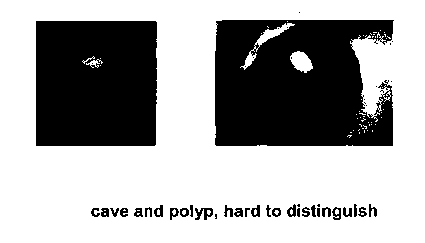
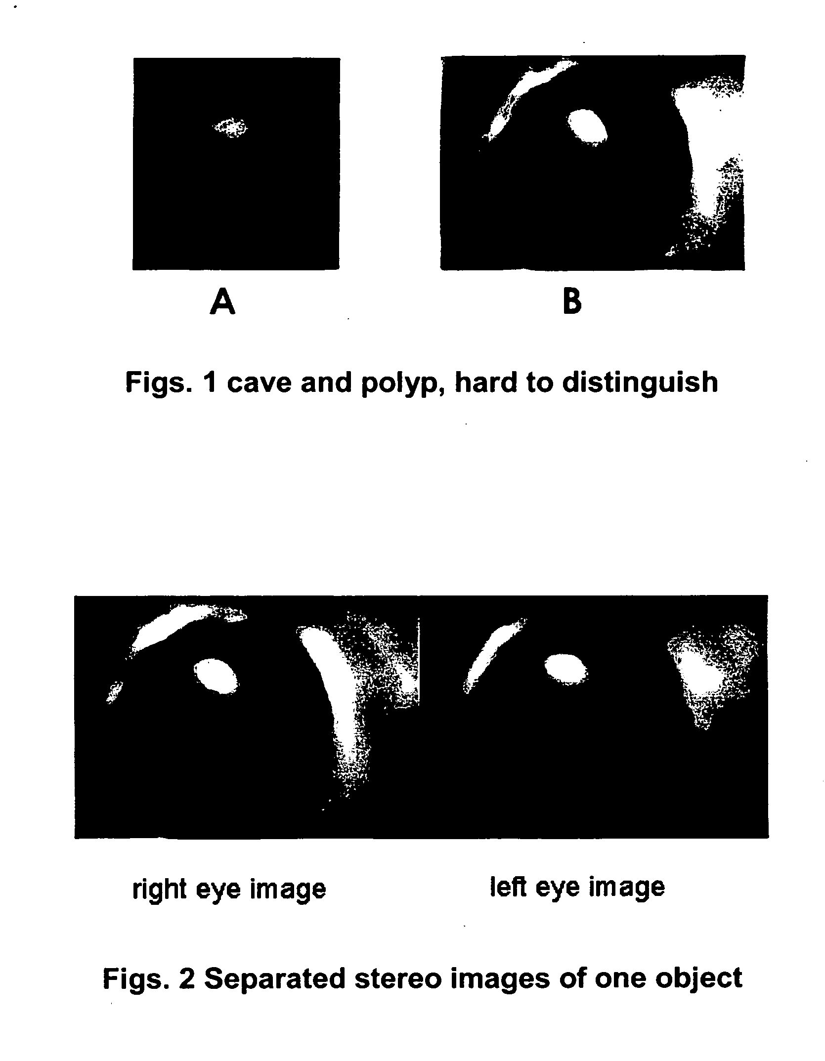
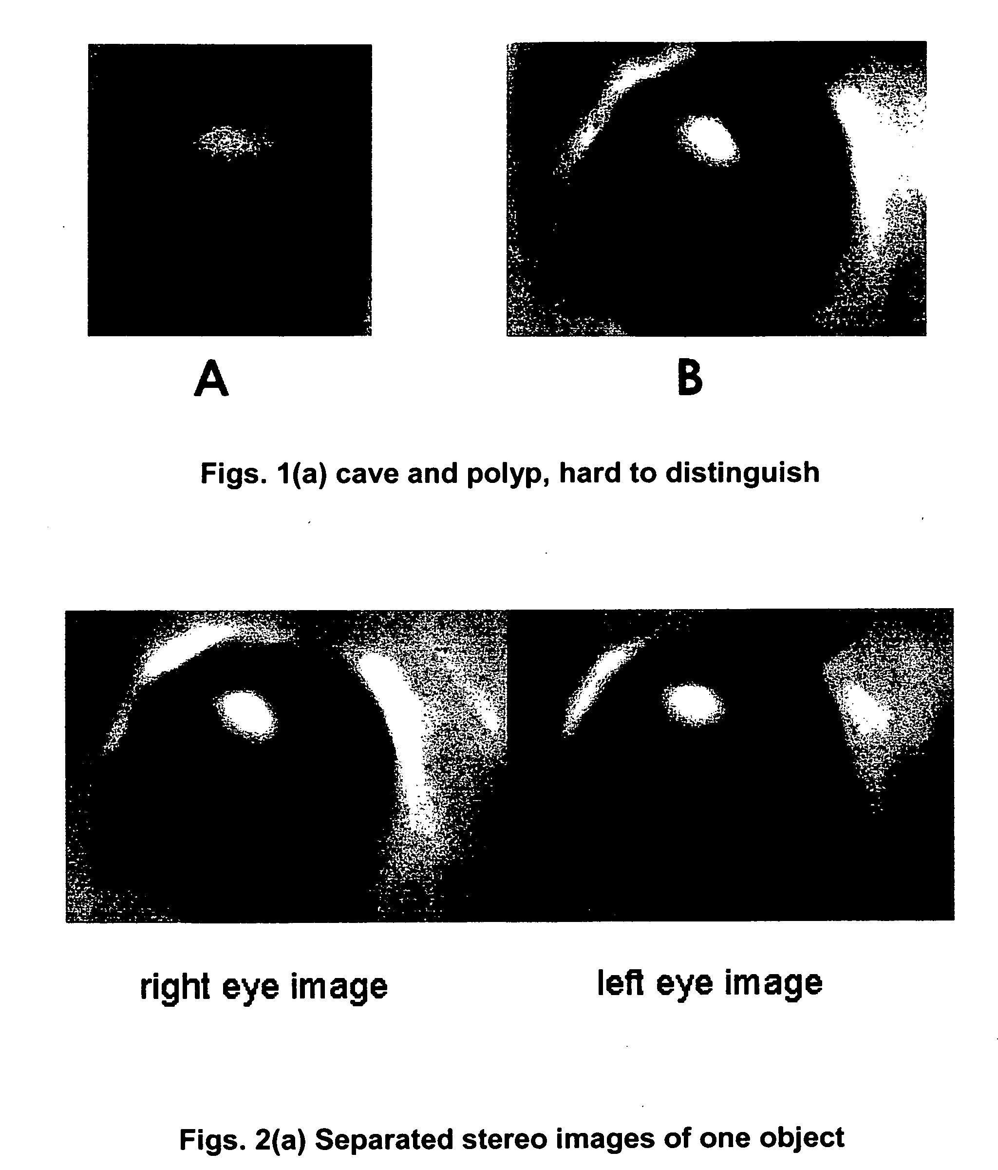
[0064] In exemplary embodiments of the present invention a ray can be constructed starting at any position in the 3D model space and ending at any other position in the 3D model space. By checking the values of each voxel that such a ray passes through relative to a defined threshold value, such an exemplary system can obtain information regarding the “visibility” of any two points. For example, as depicted in FIG. 6A, a ray can be constructed that originates at point A and terminates at point B. On its path it passes through a number of voxels. If none of those voxels has an intensity value that is larger than the given threshold value, then those voxels through which it passes are “invisible” and points A and B are visible to each other. On the other hand, if in the path taken by the ray the intensity value of a given voxel becomes larger than the threshold value, than points A and B are said to be blocked by that voxel, and are invisible to each other. Thus, the first point where...


PUM

PropertyMeasurementUnit
anatomical structureaaaaaaaaaa
timeaaaaaaaaaa
coloraaaaaaaaaa

Abstract

Improved systems and methods for stereoscopically displaying and virtually viewing tube-like anatomical structures are presented. Stereoscopic display of such structures can provide a user with better depth perception of the structure being viewed and thus make a virtual examination more real. In exemplary embodiments according to the present invention, ray shooting, coupled with appropriate error correction techniques, can be utilized for dynamic adjustment of an eye convergence point for stereo display. In exemplary embodiments of the present invention, the correctness of a convergence point can be verified to avoid a distractive and uncomfortable visualization. Additionally, in exemplary embodiments of the present invention, convergence points in consecutive time frames can be compared. If rapid changes are detected, the system can compensate by interpolating transitional convergence points. In exemplary embodiments according to the present invention ray shooting can also be utilized to display occluded areas behind folds and protrusions in the inner colon wall. In exemplary embodiments according to the present invention, interactive display control functionalities can be mapped to a gaming-type joystick or other three-dimensional controller, freeing thereby a user from the limits of a two-dimensional computer interface device such as a standard mouse or trackball.

Description

CROSS REFERENCE TO OTHER APPLICATIONS [0001] This application claims the benefit of the following United States Provisional Patent applications, the disclosure of each of which is hereby wholly incorporated herein by this reference: Ser. Nos. 60 / 517,043 and 60 / 516,998, each filed on Nov. 3, 2003, and Ser. No. 60 / 562,100, filed on Apr. 14, 2004.FIELD OF THE INVENTION [0002] This invention relates to medical imaging, and more precisely to a system and methods for improved visualization and stereographic display of three-dimensional (“3D”) data sets of tube-like anatomical structures. BACKGROUND OF THE INVENTION [0003] Historically, the only method by which a health care professional or researcher could view the inside of an anatomical tube-like structure, such as, for example, a blood vessel or a colon, was by insertion of a probe and camera, such as is done in conventional endoscopy / colonoscopy. With the advent of sophisticated imaging technologies such as magnetic resonance imaging ...

Claims


Application Information

Patent Timeline
Patent Type & Authority Applications(United States)
IPC IPC(8): A61B5/05A61B19/00G01N33/48G01N33/50G06F19/00G06T1/00G06T15/00G06T17/40G09B23/28
CPCG06T19/00G09B23/285H04N13/0275G06T2210/62G06T2219/028G06T2210/41
Inventor GUANG, YANGKEONG, EUGENE LEE CHEEKOCKRO, RALF ALFONS
Owner BRACCO IMAGINIG SPA
Learn More