
Symbol timing recovery and broadcast receiver using the same

a symbol timing recovery and receiver technology, applied in the field of broadcast receivers, can solve the problems of symbol timing recovery not being able to capture the timing offset at all, and the whole system performance is deteriorated, and the timing offset cannot be confirmed by symbol timing recovery

Inactive Publication Date: 2005-06-30
LG ELECTRONICS INC
View PDF6 Cites 21 Cited by
  • Summary
  • Abstract
  • Description
  • Claims
  • Application Information

AI Technical Summary

Benefits of technology

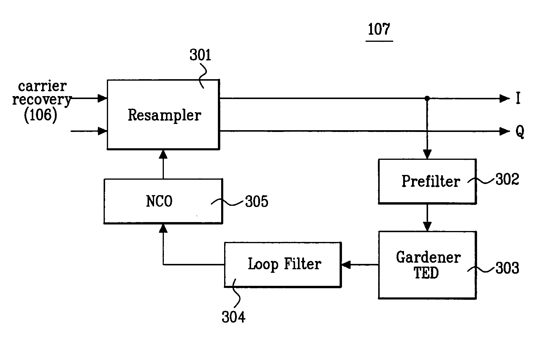
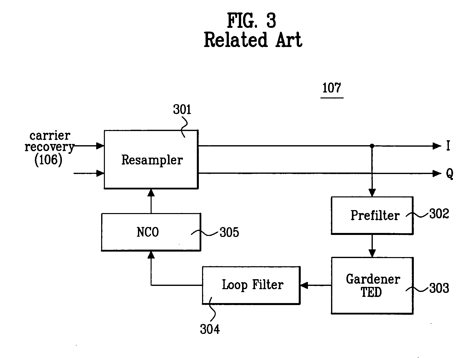
[0035] An object of the present invention is to provide a symbol timing recovery and a broadcast receiver using the same, which are capable of stably capturing a timing error even in a frequency selective fading channel such as a multi-path channel by having performance of a timing recovery not being dependent on a specific component of a frequency.
[0068] The timing error detector may estimate a value a and a timing offset value τ for minimizing the cost function J(τ) by applying the following equation: αk+1=αk-μ⁡(yi2-γ)⁢ ⁢yi⁢∂yi∂α=αk-μ⁡(yi2-γ)⁢ ⁢yi⁡(ri-j⁢ ⁢rq).τk+1=τk-μ⁡(yi2-γ)⁢ ⁢yi⁢ ⁢∂∂τk⁢yi ⁢=τk-μ⁡(yi2-γ)⁢ ⁢yi⁡(αi⁢∂∂τk⁢ri-αq⁢∂∂τk⁢rq),
[0074] The symbol timing recovery may correct the timing error by applying a fourth-degree cost function called a dispersion constant.

Problems solved by technology

If the upper band edge of the spectrum is seriously faded in a frequency selective channel circumstance, the symbol timing recovery cannot converge, thus the whole system performance is deteriorated.
As described above, if a null is generated in a relevant data edge, the symbol timing recovery has a problem of not being able to capture the timing offset at all.
Such results are represented because the average gain characteristics (S-curve) of the timing error detector is reflected as it is, by which a problem that the symbol timing recovery cannot capture the timing offset is confirmed again.
Such methods can reduce a convergence time but increases a jitter component after convergence under influence of a noise amplification, thus dose not provide a fundamental solution for a case where a symbol frequency component is seriously faded.

Method used


Image

  • Symbol timing recovery and broadcast receiver using the same
  • Symbol timing recovery and broadcast receiver using the same
  • Symbol timing recovery and broadcast receiver using the same

Examples


Embodiment Construction

[0088] Reference will now be made in detail to the preferred embodiments of the present invention, examples of which are illustrated in the accompanying drawings.

[0089] A procedure for computing, at a DMTED of the present invention, a equation of estimating a timing error will be described first in the following before a timing recovery of the present invention is described.

[0090] The present invention estimates a timing error using a constant modulus algorithm (CMA).

[0091] The CMA, which has been actively developed and is a well-established theory, has been applied to a high definition TV (HDTV) receiver as a blind equalization algorithm since the mid 1990α. The CMA is described in a document by C. Richard Johnson, titled “Blind Equalization Using the Constant Modulus Criterion: A View”, Proc. IEEE, Vol. 86, No. 10 October 1998.

[0092] The CMA converges to a direction such that a constant modulus (CM) cost function is minimized. At this point, the CM cost function comes to have ...


PUM


Abstract

A timing recovery for recovering a symbol clock using received data is provided. The timing recovery estimates a timing offset in such a way that dispersion constants of received symbols are minimized. Since the dispersion constants do not totally depend on a specific portion of a received signal spectrum, deterioration of the timing recovery performance by fading of a specific frequency component can be prevented. Particularly, the timing offset can be stably captured in a frequency selective fading channel such as a multi-path channel.

Description

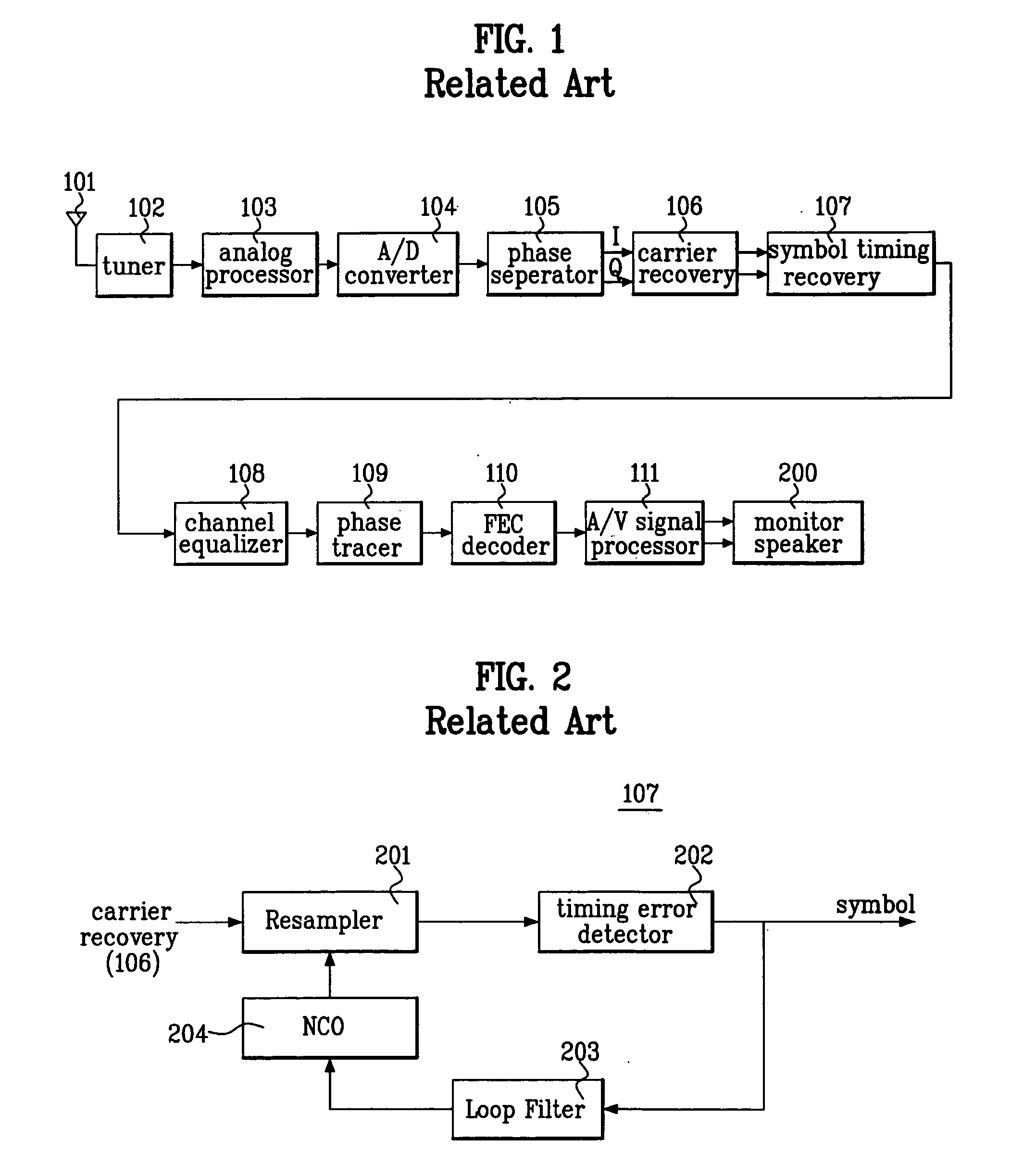
[0001] This application claims the benefit of the Korean Application No. 10-2003-0086430 filed on Dec. 1, 2004, which is hereby incorporated by reference. BACKGROUND OF THE INVENTION [0002] 1. Field of the Invention [0003] The present invention relates to a broadcast receiver, and more particularly, to a symbol timing recovery for minimizing a dispersion constant using received data. [0004] 2. Discussion of the Related Art [0005]FIG. 1 is a block diagram of a general digital receiver. Referring to FIG. 1, the digital receiver includes an antenna 101, a tuner 102, an analog processor 103, an analog / digital (A / D) converter 104, a phase separator 105, a carrier recovery 106, a symbol timing recovery 107, a channel equalizer 108, a phase tracer 109, a forward error correction (FEC) decoder 110, and an audio / video (A / V) signal processor 111. [0006] In operation, a sky-wave signal received through the antenna 101 is converted into a pass-band signal of an intermediate frequency (IF) by th...

Claims


Application Information

Patent Timeline
IPC IPC(8): H04N7/015H04L5/16H04L7/02
CPCH04L7/0054H04N7/015
Inventor KIM, JAE HYUNG
Owner LG ELECTRONICS INC
Learn More