
Comparator circuit and power supply circuit

a technology of comparator circuit and power supply circuit, which is applied in the direction of logic circuit coupling/interface arrangement, pulse technique, instruments, etc., can solve the problems of display-off operation starting, abnormal display momentarily, and display-off operation not being completed

Inactive Publication Date: 2005-06-30
SEIKO EPSON CORP
View PDF4 Cites 12 Cited by
  • Summary
  • Abstract
  • Description
  • Claims
  • Application Information

AI Technical Summary

Benefits of technology

[0014] wherein a gate electrode of the second MOS transistor is formed by polycrystalline silicon containing an n-type impurity and is connected with the first power supply line, and
[0014] wherein a gate electrode of the second MOS transistor is formed by polycrystalline silicon containing an n-type impurity and is connected with the first power supply line, and
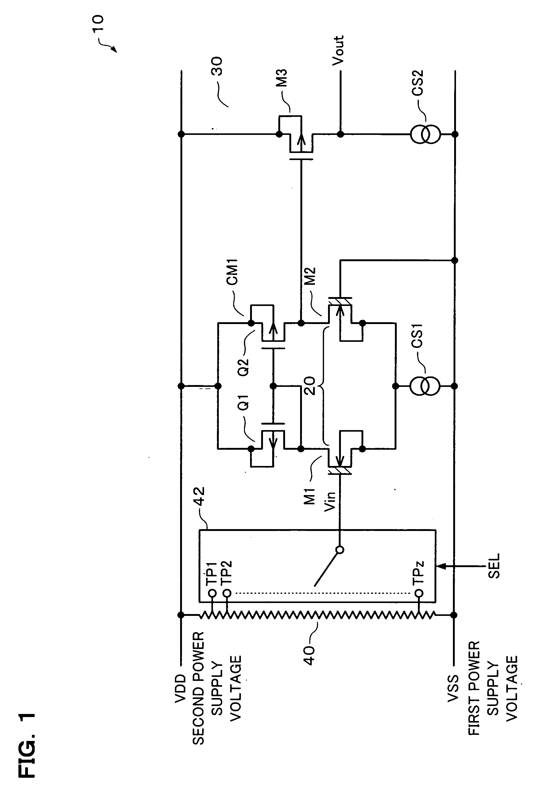
[0052] According to the present embodiment, whether or not the voltage of the input signal based on the first power supply voltage is higher than the difference in the threshold voltage between the first and second MOS transistors is detected, and the detection result is output as the output signal. A change in the input signal can be detected irrespective of a change in the second power supply voltage. Moreover, the difference in the threshold voltage between the first and second MOS transistors can be adjusted with high accuracy by the manufacturing process technology, and the temperature dependence is significantly small. Therefore, a change in the input signal can be detected with high accuracy by using a simple configuration.
[0003] An electronic instrument such as a portable telephone which includes a liquid crystal display (LCD) panel operates using a removable battery as the power supply, for example. If an electric charge remains in a boosting capacitor when the battery is removed, an abnormal display may occur momentarily (display occurs momentarily; momentary operation). Therefore, a display-off operation of controlling the voltage applied to the liquid crystal according to a predetermined sequence is performed when removing the power supply from the electronic instrument.

Problems solved by technology

If an electric charge remains in a boosting capacitor when the battery is removed, an abnormal display may occur momentarily (display occurs momentarily; momentary operation).
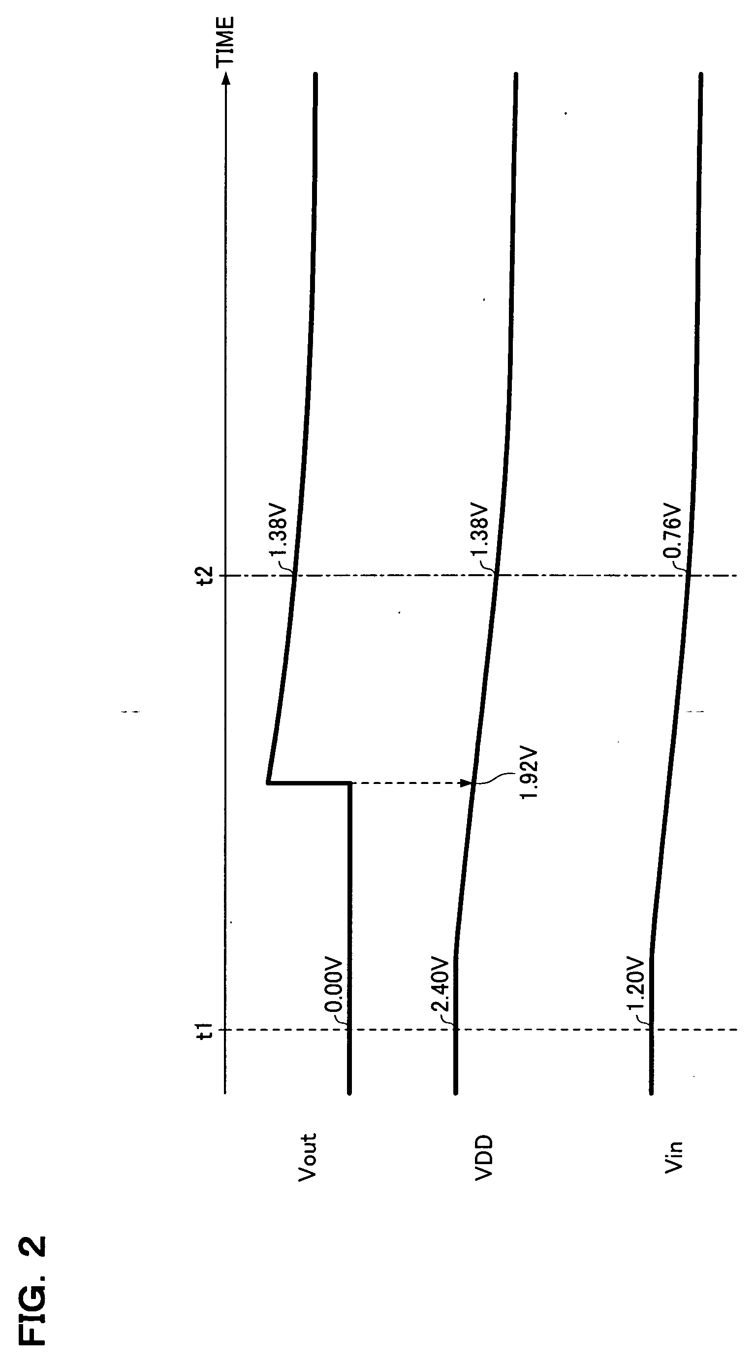
If the threshold value is high and is close to the power supply voltage during power-on, the display-off operation starts due to noise or the like.
If the threshold value is too low, the timing of judging that the battery has been removed is delayed, whereby the display-off operation cannot be completed.

Method used


Image

  • Comparator circuit and power supply circuit
  • Comparator circuit and power supply circuit
  • Comparator circuit and power supply circuit

Examples


Embodiment Construction

[0038] An embodiment of the present invention has been achieved in view of the above-described technical problem and may provide a comparator circuit and a power supply circuit which can detect a decrease in the power supply voltage with high accuracy.

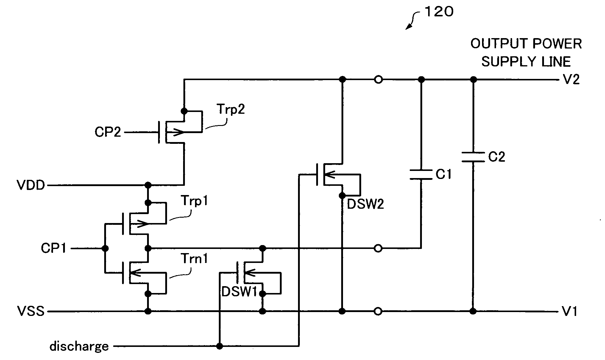
[0039] A comparator circuit according to one embodiment of the present invention includes: [0040] a differential pair which includes: [0041] a first metal oxide semiconductor (MOS) transistor of enhancement mode n-type having a gate electrode at which an input signal is supplied; and [0042] a second MOS transistor of depletion mode n-type, a source of the second MOS transistor being connected with a source of the first MOS transistor, and a threshold voltage of the second MOS transistor being lower than a threshold voltage of the first MOS transistor; [0043] a first current source inserted between a first power supply line and the differential pair, a first power supply voltage being supplied to the first power supply line; and [0044]...


PUM


Abstract

A comparator circuit includes a current mirror circuit, a differential pair, and a first current source between first and second power supply lines. The differential pair includes a first MOS transistor of enhancement mode n-type having a gate electrode at which an input signal is supplied, and a second MOS transistor of depletion mode n-type. A source of the second MOS transistor is connected with a source of the first MOS transistor and a threshold voltage of the second MOS transistor is lower than that of the first MOS transistor. A gate electrode of the first MOS transistor is formed by polycrystalline silicon which contains a p-type impurity. A gate electrode of the second MOS transistor is formed by polycrystalline silicon which contains an n-type impurity and is connected with the first power supply line. An output signal is output based on a drain voltage of the second MOS transistor.

Description

[0001] Japanese Patent Application No. 2003-429404 filed on Dec. 25, 2003, is hereby incorporated by reference in its entirety. BACKGROUND OF THE INVENTION [0002] The present invention relates to a comparator circuit and a power supply circuit using the comparator circuit. [0003] An electronic instrument such as a portable telephone which includes a liquid crystal display (LCD) panel operates using a removable battery as the power supply, for example. If an electric charge remains in a boosting capacitor when the battery is removed, an abnormal display may occur momentarily (display occurs momentarily; momentary operation). Therefore, a display-off operation of controlling the voltage applied to the liquid crystal according to a predetermined sequence is performed when removing the power supply from the electronic instrument. [0004] The display-off operation must be performed when the user or the like suddenly removes the battery when the electronic instrument operates normally in t...

Claims


Application Information

Patent Timeline
Patent Type & Authority Applications(United States)
IPC IPC(8): G01R19/165H01L27/04G05F3/02G09G3/36H01L21/822H03K5/08H03K5/24H03K17/00H03K17/30
CPCG01R19/16519H03K5/2481G01R19/16542
Inventor KAMIJO, HARUO
Owner SEIKO EPSON CORP
Learn More