Fuel injection nozzle with film-type fuel application
- Summary
- Abstract
- Description
- Claims
- Application Information
AI Technical Summary
Benefits of technology
Problems solved by technology
Method used
Image
Examples
Embodiment Construction
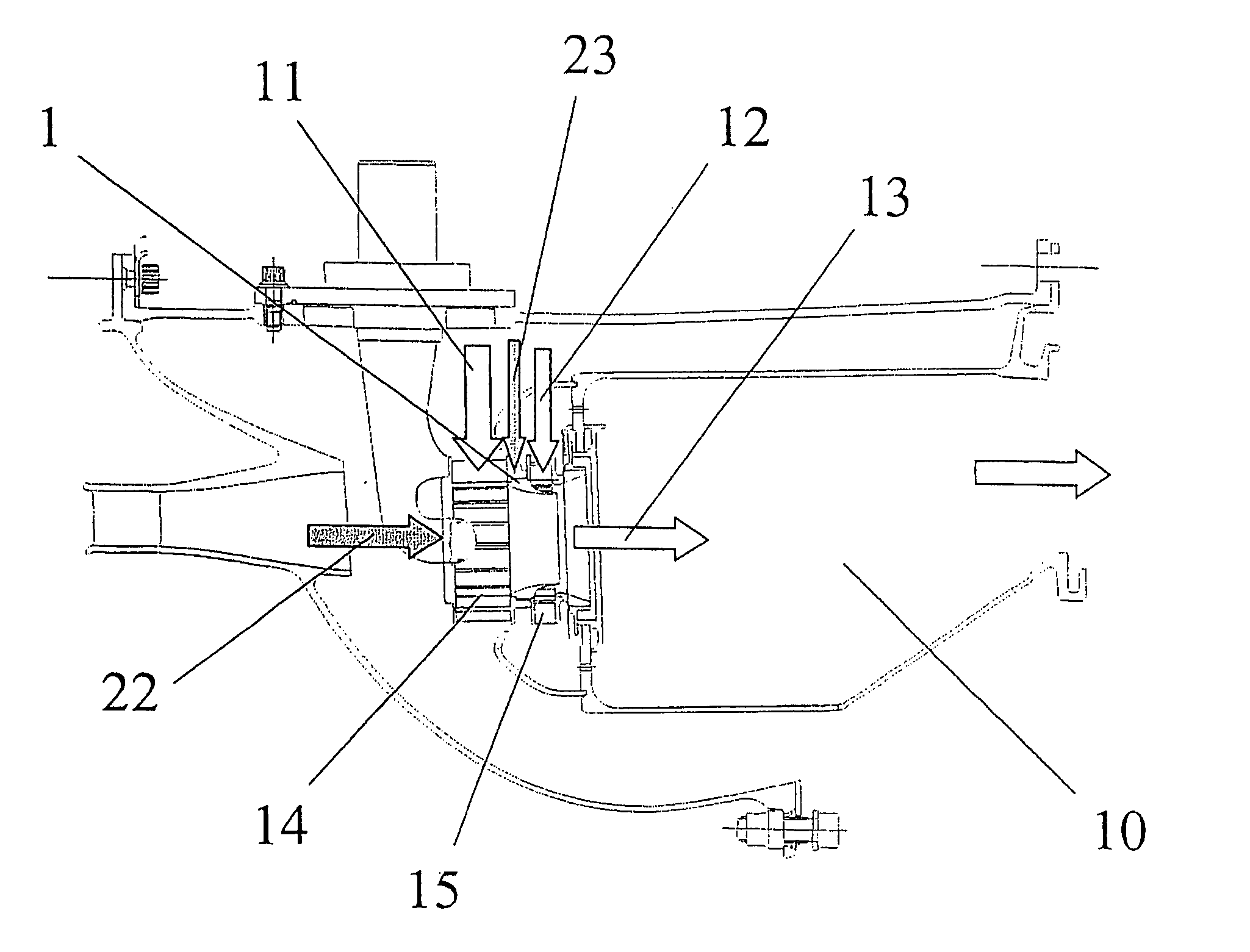
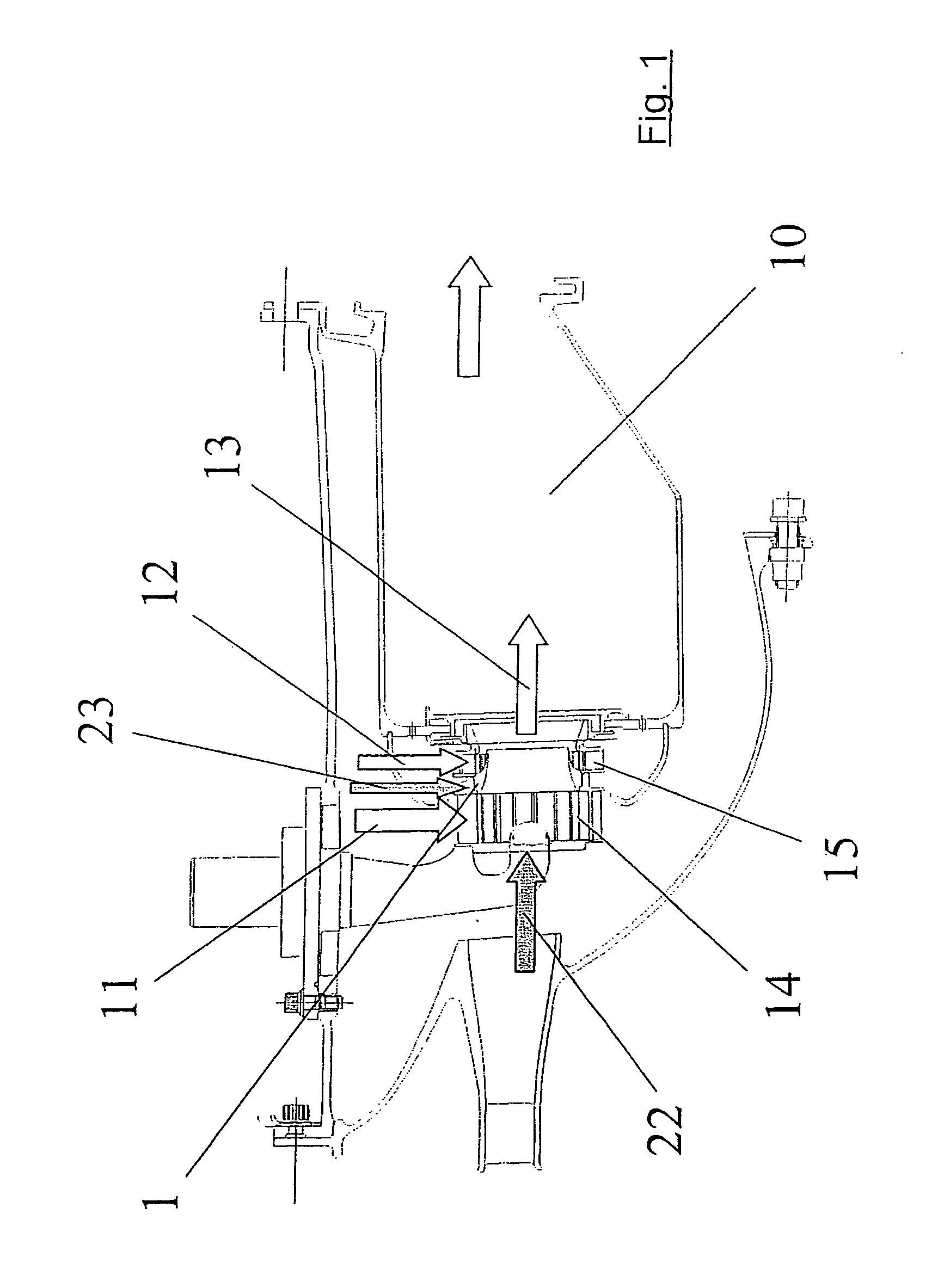
[0033] In the figures, like items are identified with like reference numerals.
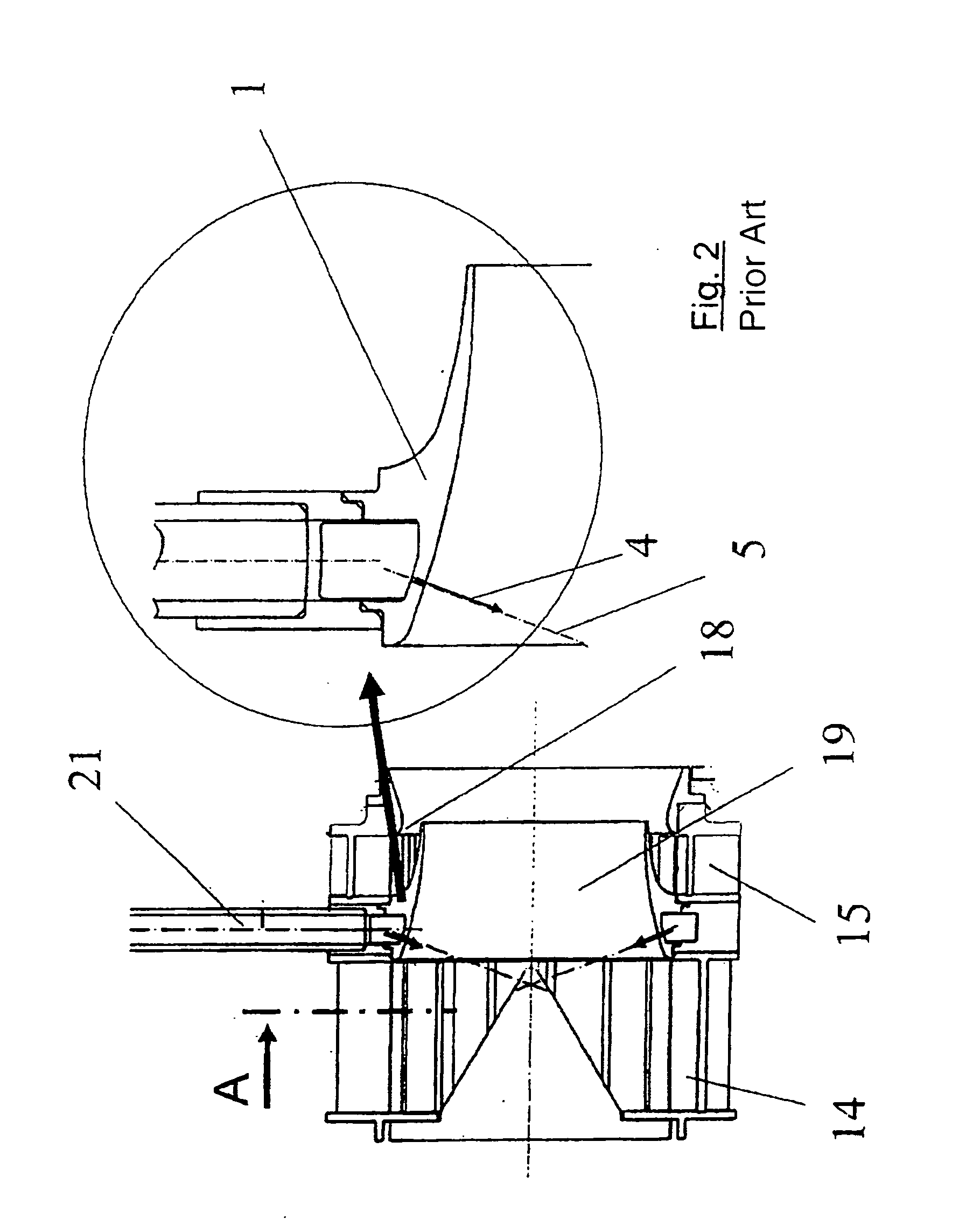
[0034]FIG. 3 shows, in simplified representation, a section through a film applicator 1 in accordance with the present invention, with fuel openings 2, in particular fuel holes 3, being illustrated whose center axes 5 are inclined at an angle α to the main flow direction 6 (near-wall flow direction in the inner swirl channel).
[0035] Reference numeral 16 indicates a yawing wall element of the film applicator 1, reference numeral 17 an aerodynamically conformal film applicator surface. Reference numeral 21 indicates a fuel line.
[0036] With the present invention, unintentional penetration of liquid fuel into areas with low flow velocities and the resultant non-uniform mixture of fuel and air are avoided. FIG. 3 shows a proposed embodiment. Here, the fuel is not injected radially inward, i.e. with a high radial component of the exit velocity of the fuel, into an inner swirl channel. Rather, a high axial com...
PUM
 Abstract
Description
Claims
Application Information
 - R&D
- Intellectual Property
- Life Sciences
- Materials
- Tech Scout
- Unparalleled Data Quality
- Higher Quality Content
- 60% Fewer Hallucinations
Browse by: Latest US Patents, China's latest patents, Technical Efficacy Thesaurus, Application Domain, Technology Topic, Popular Technical Reports.
© 2025 PatSnap. All rights reserved.Legal|Privacy policy|Modern Slavery Act Transparency Statement|Sitemap|About US| Contact US: help@patsnap.com


