
Pipeline-based circuit with a postponed clock-gating mechanism for reducing power consumption and related driving method thereof

a technology of power consumption and clock-gating mechanism, which is applied in the direction of generating/distributing signals, pulse techniques, instruments, etc., can solve the problems of mainly generated unnecessarily increasing power consumption of logic circuits, and all of the circuit units within logic circuits are not always active, so as to achieve simple circuit structure of second buffer units and achieve successful power saving.

Inactive Publication Date: 2005-06-16
NOVATEK MICROELECTRONICS CORP
View PDF6 Cites 10 Cited by
  • Summary
  • Abstract
  • Description
  • Claims
  • Application Information

AI Technical Summary

Benefits of technology

This approach prevents late-arrived control signals from affecting the clock-gating unit, allows for successful power-saving gating, and maintains pipeline clock speed without significant increases in power consumption, even with different pipeline structures.

Problems solved by technology

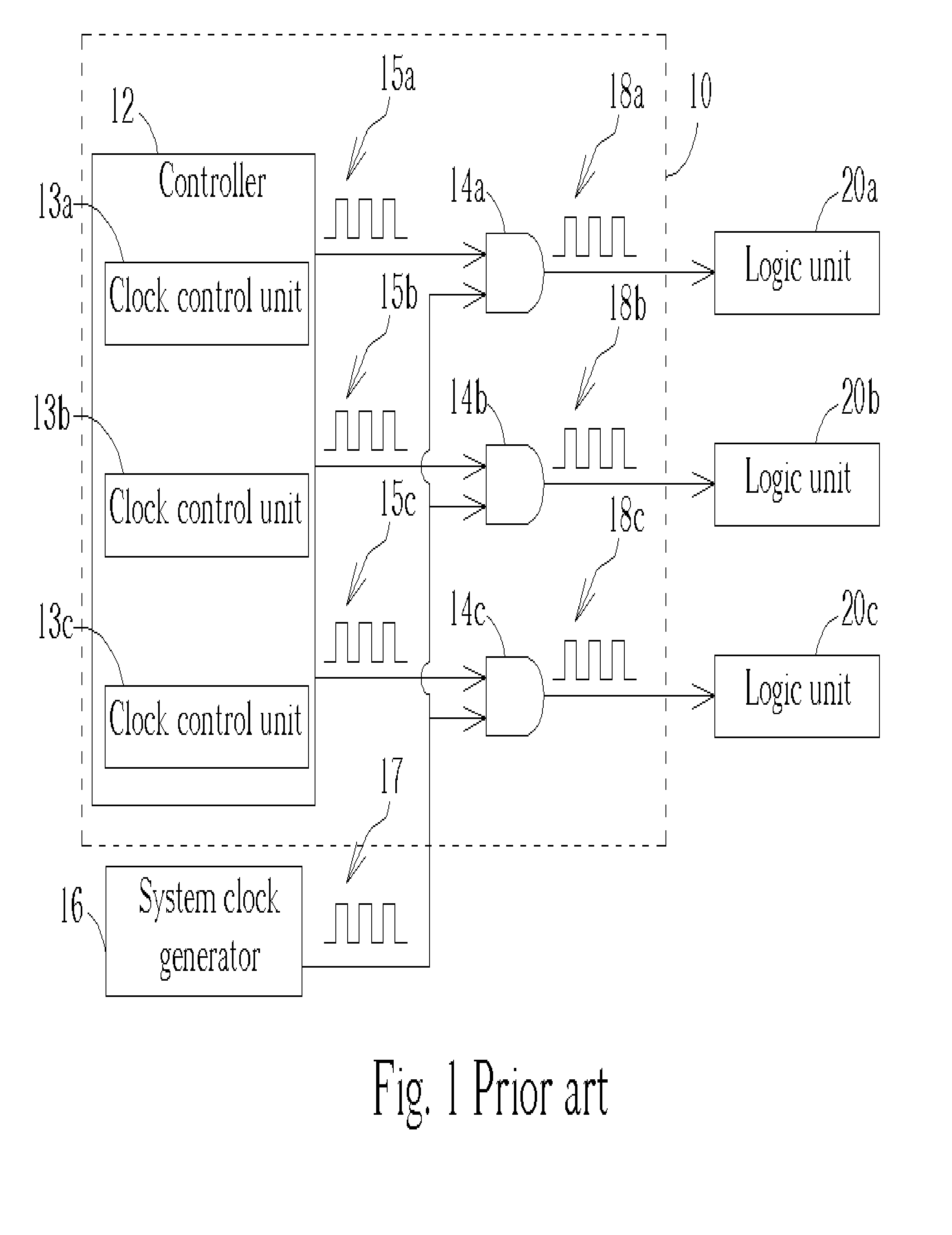
However, all of the circuit units within the logic circuit are not always active.
If the clock signal is still inputted into the idle circuit units, power consumption of the logic circuit is increased unnecessarily.
It is well known that the power consumption of the logic circuit is mainly generated from delivering the clock signal to these circuit units and enabling these circuit units to run related logic operations.
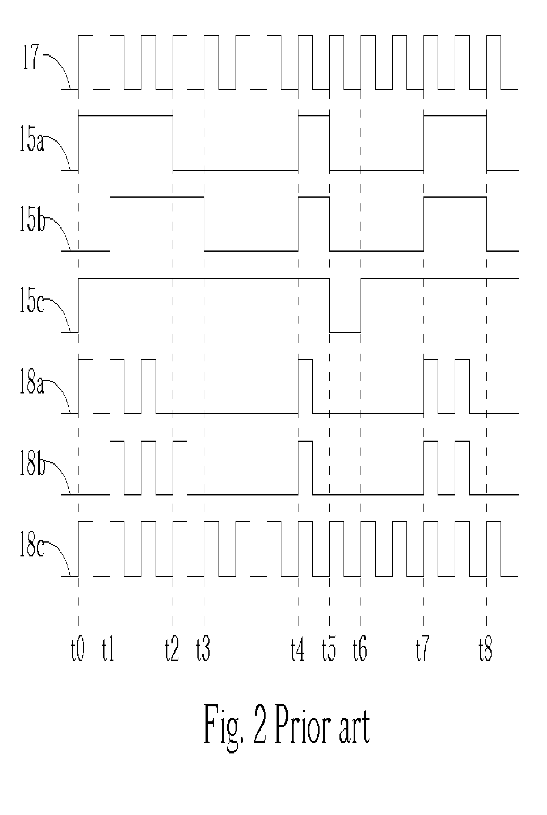
Furthermore, a glitch is induced to affect the operation of the processing unit 32b.
The unwanted glitch induced for each of the clock signals CLK_GA, CLK_GB, CLK_GC likely results in the pipeline-based logic circuit 30 functioning incorrectly.

Method used


Image

  • Pipeline-based circuit with a postponed clock-gating mechanism for reducing power consumption and related driving method thereof
  • Pipeline-based circuit with a postponed clock-gating mechanism for reducing power consumption and related driving method thereof
  • Pipeline-based circuit with a postponed clock-gating mechanism for reducing power consumption and related driving method thereof

Examples


Embodiment Construction

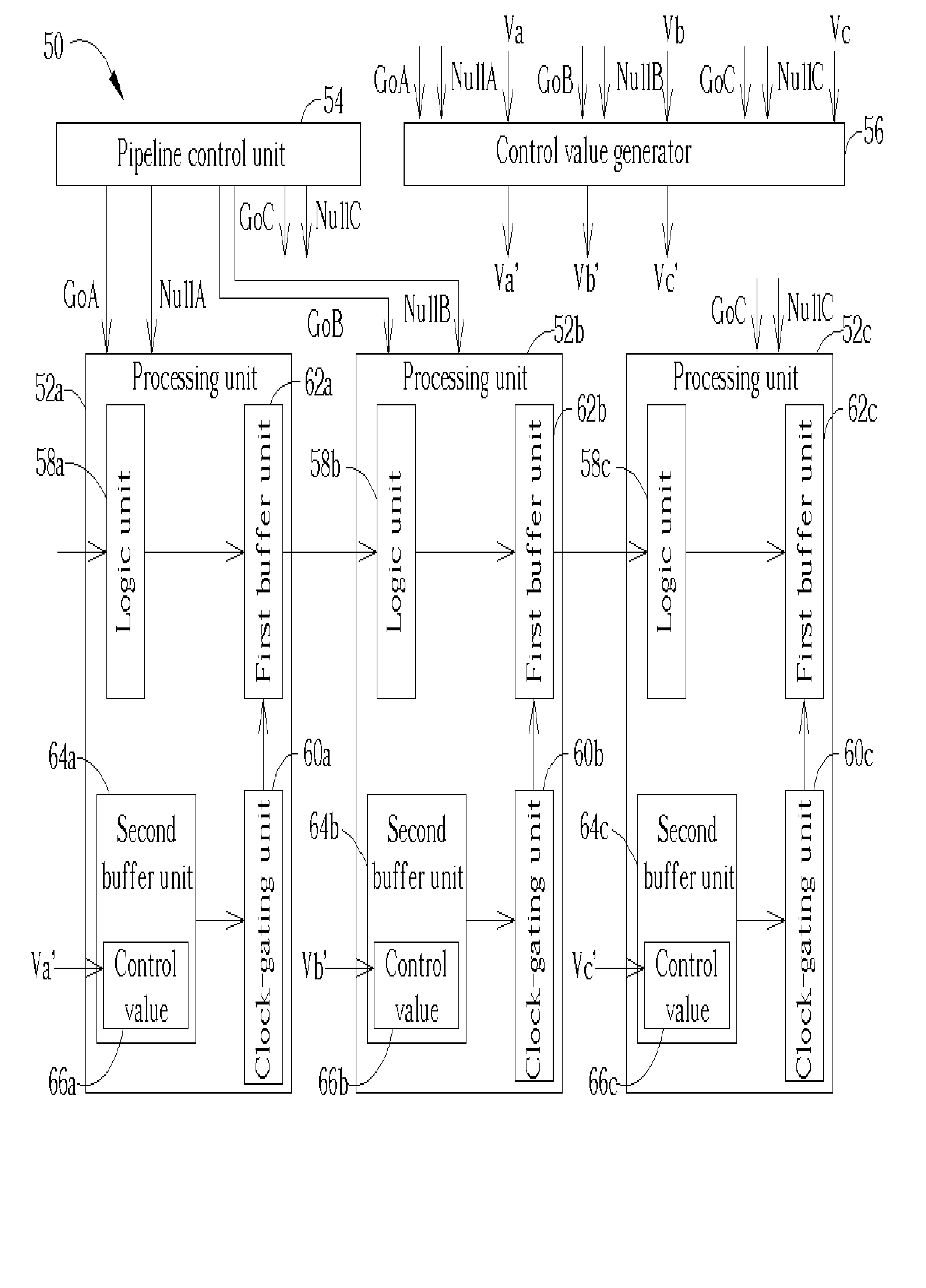
[0024] Please refer to FIG. 6, which is a block diagram of a pipeline-based circuit 50 according to the present invention. The pipeline-based circuit 50, which can be a microprocessor or a digital signal processor (DSP), has a plurality of processing units 52a, 52b, 52c, a pipeline control unit 54, and a control value generator 56. The processing units 52a, 52b, 52c are cascaded to establish a pipeline. Each of the processing units 52a, 52b, 52c has a logic unit 58a, 58b, 58c, a clock-gating unit 60a, 60b, 60c, a first buffer unit 62a, 62b, 62c, and a second buffer unit 64a, 64b, 64c. Taking the processing unit 52a for example, the logic unit 58a is used to perform a predetermined logic operation such as addition or multiplication. The first buffer unit 62a is used to store a calculation result outputted from the logic unit 58a, and to pass the stored calculation result to the next processing unit 52b. The clock-gating unit 60 is used to control a clock signal inputted into the firs...


PUM


Abstract

A pipeline-based circuit with a postponed clock-gating mechanism and related driving method are disclosed for reducing power consumption, and the driving method does not deteriorate processing performance of the pipeline-based circuit. A pipeline-based circuit has a plurality of logic operators cascaded to form at least a pipeline, a pipeline control unit for generating at least a control signal to each logic operator for controlling whether one logic operator needs to pipe data to next logic operator, and a control value calculator for setting a valid bit of each logic operator following a currently activated logic operator according to the control signals generated from the pipeline control unit. When each logic operator begins operating, the related control value is used to determine whether or not a clock signal piping data of the present logic operator to next logic operator is gated to reduce power consumption. This postponed clock-gating mechanism avoids the degradation of pipeline clock speed limitation.

Description

BACKGROUND OF INVENTION [0001] 1. Field of the Invention [0002] The present invention relates to a pipeline-based circuit. In particular, the present invention discloses a pipeline-based circuit utilizing a postponed clock-gating mechanism for reducing power consumption. [0003] 2. Description of the Prior Art [0004] An accurate clock signal is a key factor for a logic circuit to perform a correct logic operation. That is, the clock signal is used to drive kernel circuit units such as counters and registers within the logic circuit, and a stable clock signal such as a clock signal generated from a crystal oscillator always functions as a reference clock to arbitrate operations of the circuit units within the logic circuit. However, all of the circuit units within the logic circuit are not always active. When some of the circuit units enter an idle mode, these idle circuit units do not need to be driven by the clock signal continuously for performing related operations. If the clock s...

Claims


Application Information

Patent Timeline
Patent Type & Authority Applications(United States)
IPC IPC(8): G06F1/32G06F9/38H03K19/00
CPCG06F1/3203Y02B60/1221G06F9/3869G06F1/3237Y02D10/00
Inventor CHEN, CHUNG-HUI
Owner NOVATEK MICROELECTRONICS CORP
Learn More