
Energy management head restraint insert

a head restraint and energy management technology, applied in the field of head restraints in motor vehicles, can solve the problems of increasing neck force, soft foam, and insufficient structure of head restraints, and achieve the effect of reducing neck injuries

Inactive Publication Date: 2005-06-16
LEAR CORP
View PDF21 Cites 45 Cited by
  • Summary
  • Abstract
  • Description
  • Claims
  • Application Information

AI Technical Summary

Benefits of technology

[0006] The object of this invention is to overcome the above-mentioned problems with current head restraints. A floating insert of a somewhat rigid material would help reduce neck injuries and help meet safety regulations.
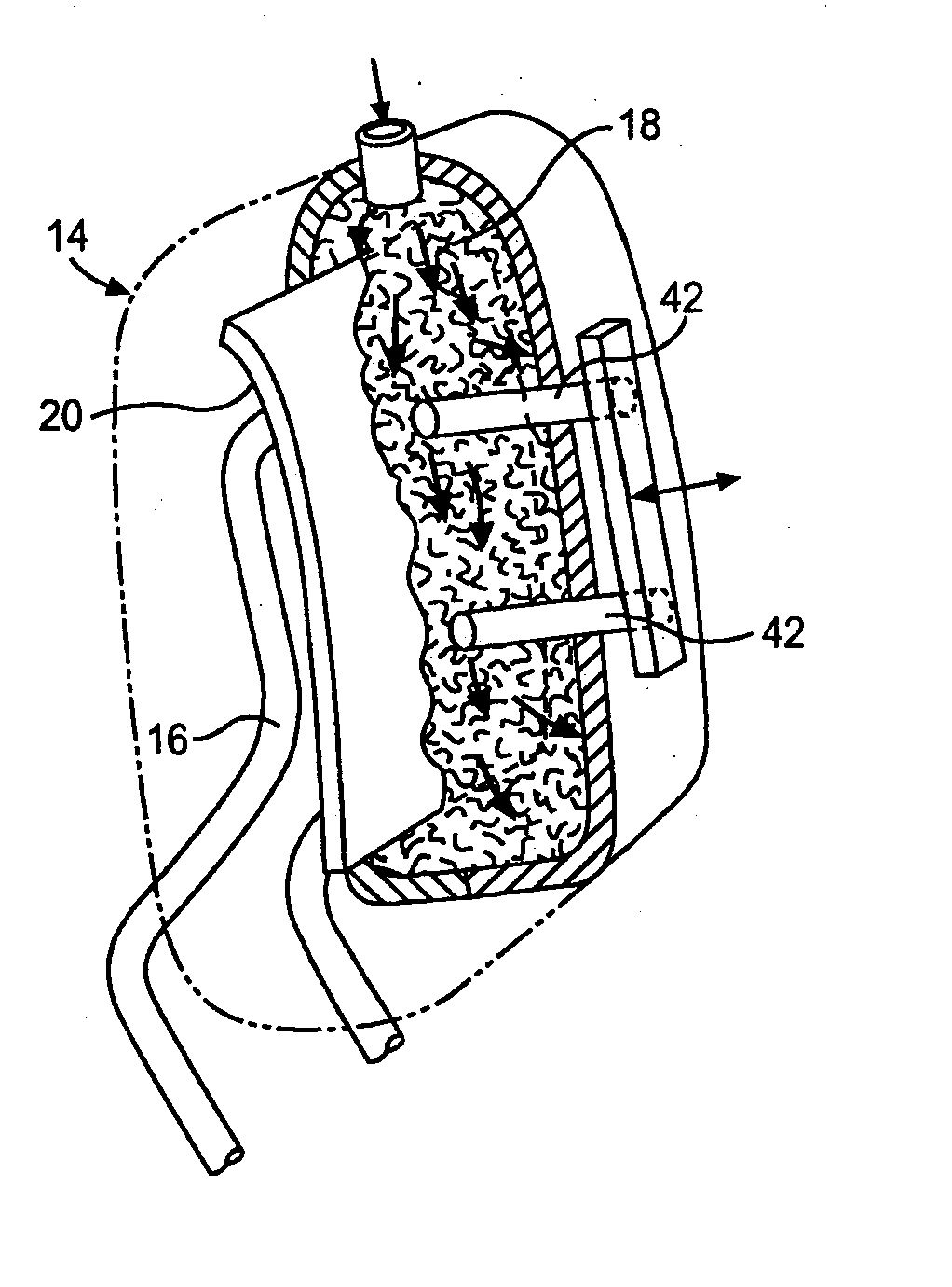
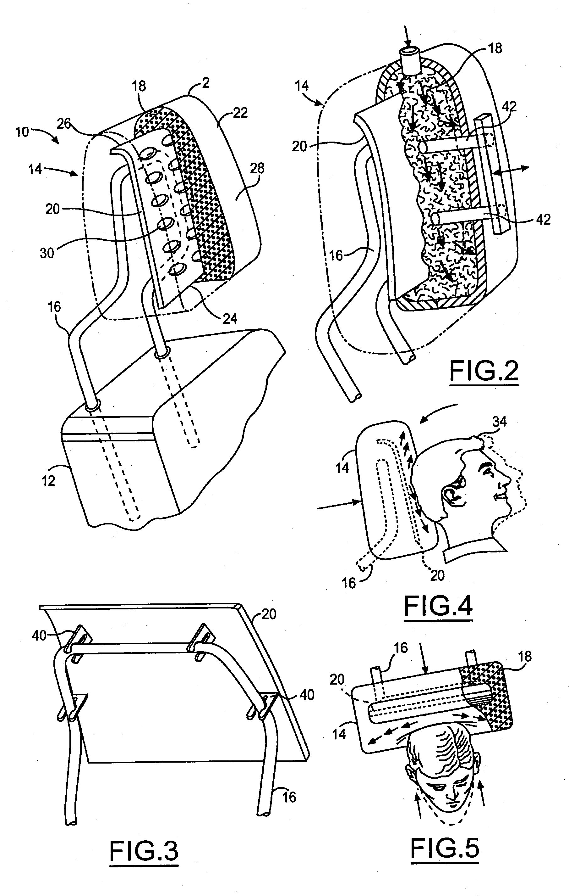
[0008] This invention solves the above-mentioned problems by using an insert that possesses good elastic properties. This insert in head restraints provides a more uniform stiffness and energy management without having to change foam or posts in current head restraints. It will also provide a more uniform loading surface for an occupants head. Unlike many inserts that are rigidly attached to the post or other seat back structure, this insert is allowed to move relative to the structure under test or crash conditions. This action controls the acceleration of the head to reduce the peak magnitude while simultaneously minimizing the penetration. The effect is to reduce forces and moments on the neck as well as to reduce the head rotation relative to the torso.
[0010] Additionally, the elasticity of the insert would help head restraints to meet the deflection criteria for backset retention and height retention. The insert will assist the foam recovery so that the foam will return to acceptable limits within a reasonable time after the loading event.

Problems solved by technology

A problem with this design is that the foam is often times too soft and does not provide adequate structure within the head restraint.
In the event of a rear impact, the head may penetrate too deeply between or above the post structure, increasing the forces on the neck.
Soft foam has a slow recovery time.
As a result, many head restraints do not meet some safety standards imposed on motor vehicle manufacturers.

Method used


Image

  • Energy management head restraint insert
  • Energy management head restraint insert
  • Energy management head restraint insert

Examples


Embodiment Construction

[0017] With reference to FIG. 1, this invention comprises a post 4, foam 6, an insert 8, and trim cover 14 creating head restraint 2. This insert 8 that is the object of this invention will be sized to fit any variety of head restraints. Generally, head restraints use an M or U shaped post but the insert 8 can be designed to fit any shaped post.

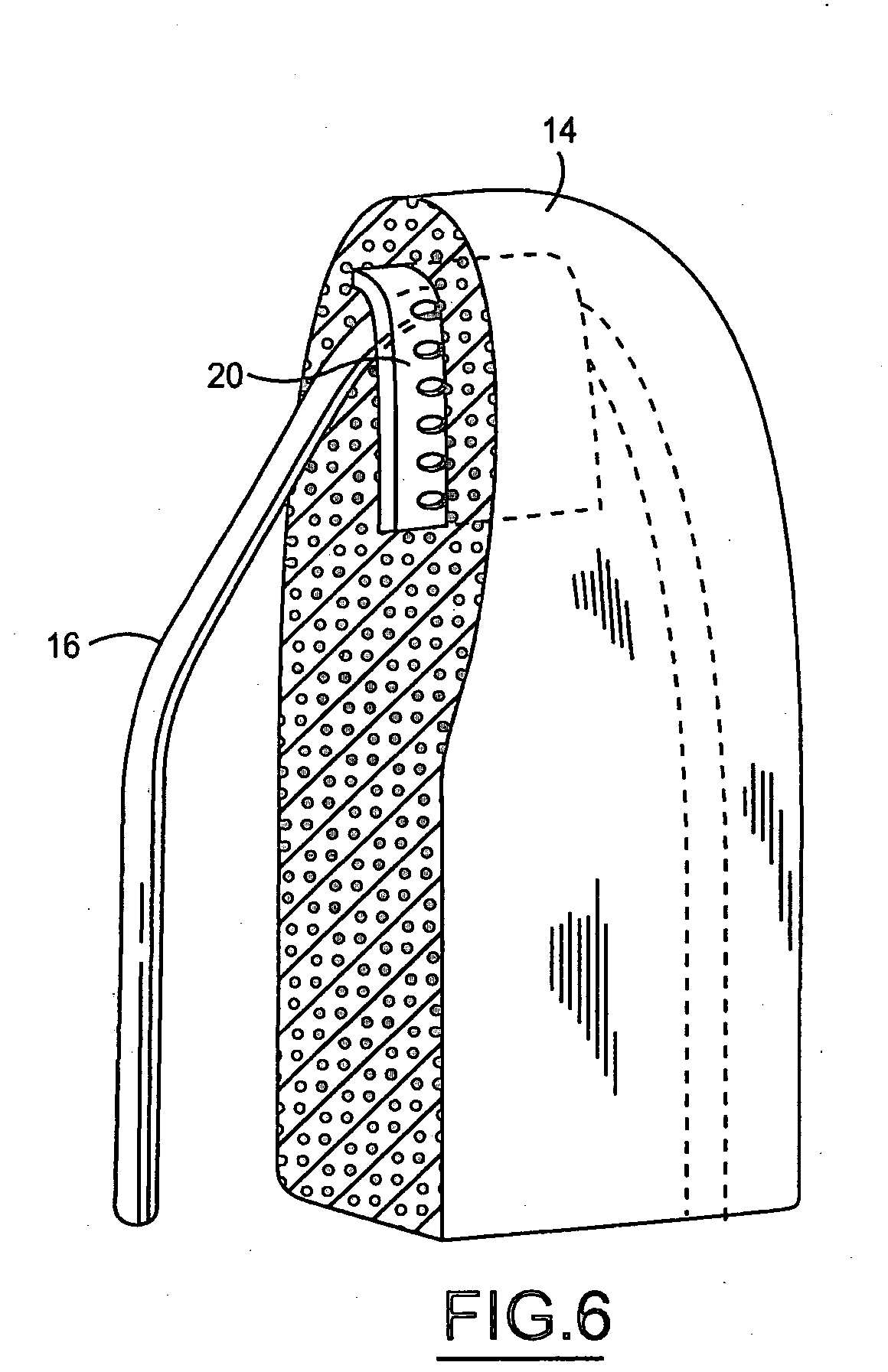
[0018] The insert 8 is molded into the foam 6 on the front side of the post 4 at some nominal distance below the surface of the head restraint 2. The insert 8 needs to be buried within the foam 6 so that the head restraint 2 still is comfortable for occupants. This insert 8 also needs to cover a majority of the front surface area and top of the head restraint 2. The insert 8 could also be formed to fit a variety of head restraint contour designs. Additionally, the insert 8 can comprise of plastic, metal, or a composite material. The versatility of the designs for this insert 8 allow it to be used in most if not all head restraints.

[0019] Th...


PUM


Abstract

An head restraint with an insert on seats in motor vehicles whereby said head restraint controls occupant's head acceleration and reduces neck loading in cases of impact. This head restraint comprises a post of any shape inserted into a seatback, foam of a desired thickness, an insert sized to cover a majority of the surface area on the front face and top of said head restraint, and a trim cover. Alternatively, the head restraint may be of integral design without posts. The insert is meant to float within foam in the head restraint and one can use clips or locating pins during manufacturing to obtain desired floating effect.

Description

FIELD OF INVENTION [0001] This invention relates to head restraints in motor vehicles. More specifically, it relates to a safer head restraint and manufacturing thereof by utilizing a floating insert to increase head restraint stiffness and energy management without necessarily changing the foam or posts of traditional head restraints. BACKGROUND OF INVENTION [0002] Today, most, if not all, motor vehicles come with seats equipped with head restraints. Head restraints provide not only comfort for riders but also are there to protect an occupant's head and neck in case of an accident. [0003] Many current head restraints use U or M shaped posts with foam covering the posts. These head restraints simply have the foam interior molded around the posts. See U.S. Pat. No. 6,120,100 for an example. A problem with this design is that the foam is often times too soft and does not provide adequate structure within the head restraint. In the event of a rear impact, the head may penetrate too dee...

Claims


Application Information

Patent Timeline
IPC IPC(8): A47C1/10B60N2/48
CPCB60N2/4885B60N2/888
Inventor VEINE, ERICLOCKE, GERALD S.
Owner LEAR CORP
Learn More