
Rolling tarp enclosure system

a technology of tarp enclosure and tarp cover, which is applied in the direction of roofs, transportation and packaging, vehicle components, etc., can solve the problems of shortening the useful life of the wheels, difficult to fully tension the tarp cover to the upper end, and affecting the safety of use, so as to improve the safety and safety of use and adjustment, the effect of simplifying the construction process and saving the cos

Active Publication Date: 2018-02-06
DEMONTE WALTER PETER +2
View PDF24 Cites 5 Cited by
  • Summary
  • Abstract
  • Description
  • Claims
  • Application Information

AI Technical Summary

Benefits of technology

The solution enhances tensioning capabilities, extends wheel durability, simplifies installation and operation, reduces system complexity and cost, and maintains cargo space while handling larger and heavier tarp covers under external forces.

Problems solved by technology

While such previously disclosed tensioning mechanisms function appropriately for tensioning the tarp cover, they have limitations associated therewith.
For example, while the applicant's prior locking tensioning mechanism in U.S. Pat. Nos. 7,854,465 and 8,047,600 functions appropriately to tension the tarp cover, it only engages the rearmost carriage at the bottom portion of the tarp cover which makes it somewhat challenging to tension the tarp cover fully to the upper end thereof.
This is acceptable, but some additional means should be provided to prevent any undue or unbalanced forces from being applied to the wheels of the rearmost rolling carriage because undue or unbalanced forces would significantly shorten the useful life of the wheels.
Conversely, the applicant's rolling tarp system, commercially sold under the trademark Quick Draw™, has rolling carriages with wheels that roll along the top of the rail, and hence cannot use the Loc-N-Load Mechanism because it would interfere with movements of the rearmost rolling carriage.
However, it also has some limitations associated therewith.
This creates some difficulties during initial installation of locking and tensioning mechanism 100, as well as throughout the life of the tarp cover system as it may become necessary for a driver to remove and re-install, or reposition the locking and tensioning mechanism 100 on location wherever the trailer may be disposed at any given time.
This complicates the work required by persons installing and operating the system, and may lead to safety issues if done too hastily or otherwise improperly.
Such flatbed trailers may also be equipped with rolling type tarp cover systems, but such systems have conventionally required a second section of rail for being disposed at the higher level and extra rolling carriages for rolling on the second section of rail at the higher level, and / or other modifications in order to permit the tarp cover to be fully moved in the front or rear direction, which significantly increases the cost of the system.
Also, the second section of rail may interfere with some movements of the system.
Even with the rolling carriages with wheels that roll on top of the rail, however, there are practical limits on the size and durability of same.
Also, some rolling tarp systems are quite large and / or exposed to particularly significant external forces during use, such that there is a desire for a rolling carriage that can be reliably used with the larger systems and with systems that are exposed to particularly significant external forces during use.
Further, with the vehicle-mounted rolling tarp systems there is often a need for additionally securing the cargo disposed on the flatbed trailer within the rolling tarp system, e.g., if the cargo's weight and / or shape tends to make it unstable.
Disposition of the additional securing mechanisms within the tarp cover system, however, undesirably reduces the amount of usable cargo space within the tarp cover systems.
Hence, there is a need for an additional securing mechanism which can be appropriately used with the rolling tarp cover systems, but which minimally reduce the amount of usable cargo space within the tarp cover systems and meet government regulations.
While the previously proposed system including such support bows 114 and lifter bows 112 functions very well in supporting the tarp cover in the applicant's previously proposed system, the cost of same is significant.

Method used


Image

  • Rolling tarp enclosure system
  • Rolling tarp enclosure system
  • Rolling tarp enclosure system

Examples


Embodiment Construction

[0067]A number of selected illustrative and exemplary embodiments of the invention will now be described in some detail, with reference to the drawings. It should be understood that only structures considered necessary for clarifying the present invention are described herein. Other conventional structures, and those of ancillary and auxiliary components of the system, are presumed to be known and understood by those skilled in the art. These illustrative embodiments include locking and tensioning devices for tarp enclosure systems being mounted on flatbed trailers, other vehicles or the like, and various components of such systems.

Movable Rail for Systems Used on Drop Deck Trailers

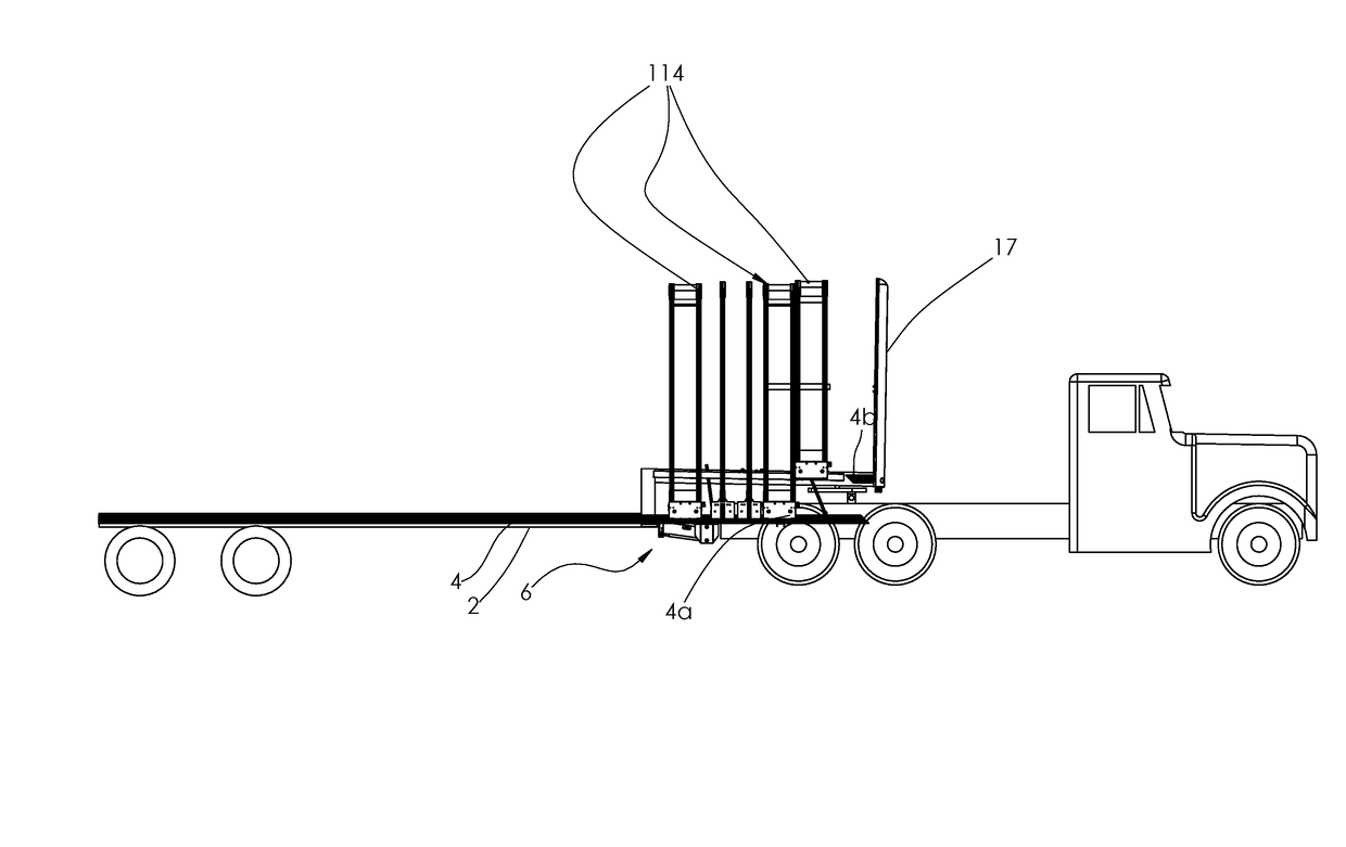
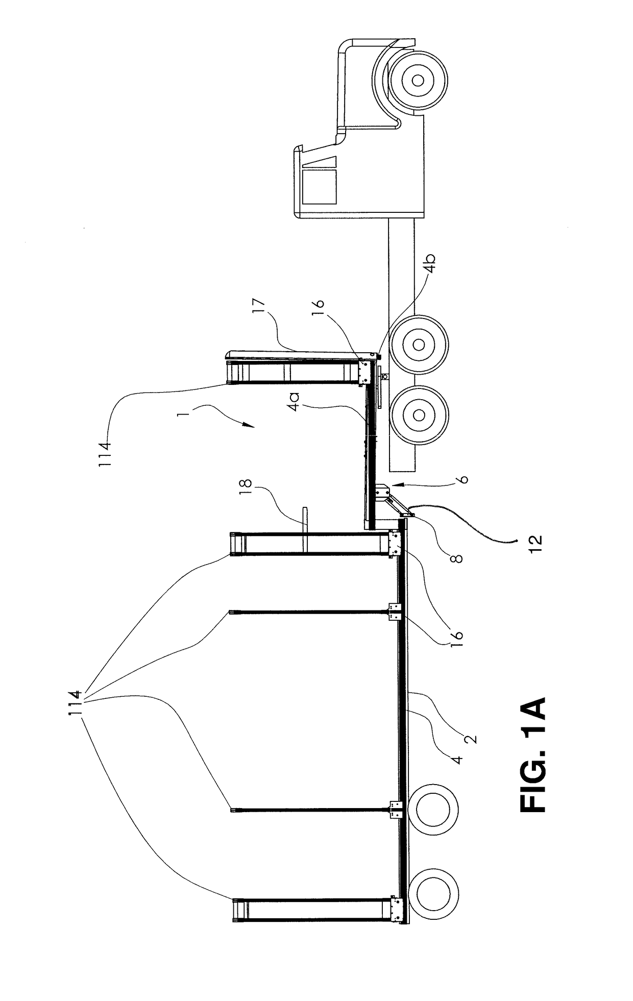
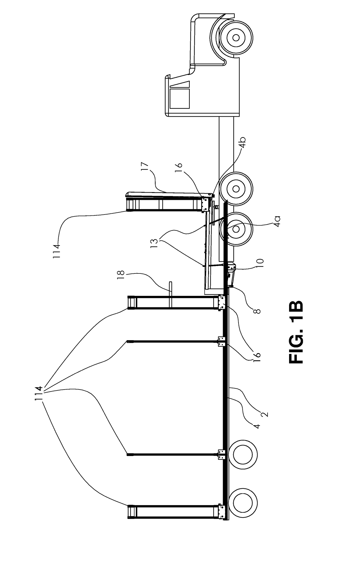
[0068]Referring now to FIGS. 1A-1E of the drawings, there are shown side elevational views of a rolling type tarp cover system 1 disposed in various positions on a drop deck type flatbed trailer 2 according to an exemplary embodiment of the present invention. In these figures a tarp cover, which is an out...


PUM


Abstract

A support rail for a movable, flatbed trailer-mounted tarp enclosure system having a tarp cover, a plurality of substantially U-shaped bows connected to and supporting the tarp cover, and rolling carriages connected to lower ends of said bows and which roll along the support rail, the support rail including a first elongate rail section which is fixed to the trailer and extends substantially parallel to a cargo support surface of the trailer, a second elongate rail section which is movably connected to the trailer, and a support mechanism which connects the second elongate rail section to the trailer such that the second elongate rail section may be moved between a first position extending continuously to the first elongate rail section along a common axis and a second position parallel to but at a different level from the first elongate rail section.

Description

BACKGROUND OF THE INVENTION1. Field of the Invention[0001]This invention relates to an improved rolling tarp enclosure system. More particularly, the invention relates to several improvements for a retractable tarp enclosure system which may be used for covering substantially any area or object, including swimming pools, beds of trucks, flatbed trailers and the like. More particularly, the present invention relates to such a rolling tarp enclosure system with improvements to a rail and rolling carriage arrangement thereof, to tensioning arrangements thereof, to corner portions of end sections thereof, and to other aspects of the rolling tarp enclosure system.2. Discussion of Background Art[0002]Rolling tarp covering and enclosure systems have long been known for use in a wide variety of applications, including tents, greenhouses and other space enclosures, awnings, swimming pool covers, vehicle load covers, etc. When such systems are provided on vehicles such as flatbed trailers, so...

Claims


Application Information

Patent Timeline
Patent Type & Authority Patents(United States)
IPC IPC(8): B60J7/02B60J7/06
CPCB60J7/06B60J7/022B60J7/065B60J7/185B60J7/104B60J7/1855
Inventor DEMONTE, WALTER PETERDEMONTE, TIMOTHY PAULLEBLANC, SHERI LYN
Owner DEMONTE WALTER PETER
Learn More