
Continuous slurry dispenser apparatus

a dispenser and continuous technology, applied in the direction of lighting and heating apparatus, combustion types, transportation and packaging, etc., can solve the problems of clogging of passageways in the dispensing apparatus, premature setting of slurry,

Inactive Publication Date: 2005-06-16
UNITED STATES GYPSUM CO
View PDF33 Cites 16 Cited by
  • Summary
  • Abstract
  • Description
  • Claims
  • Application Information

AI Technical Summary

Benefits of technology

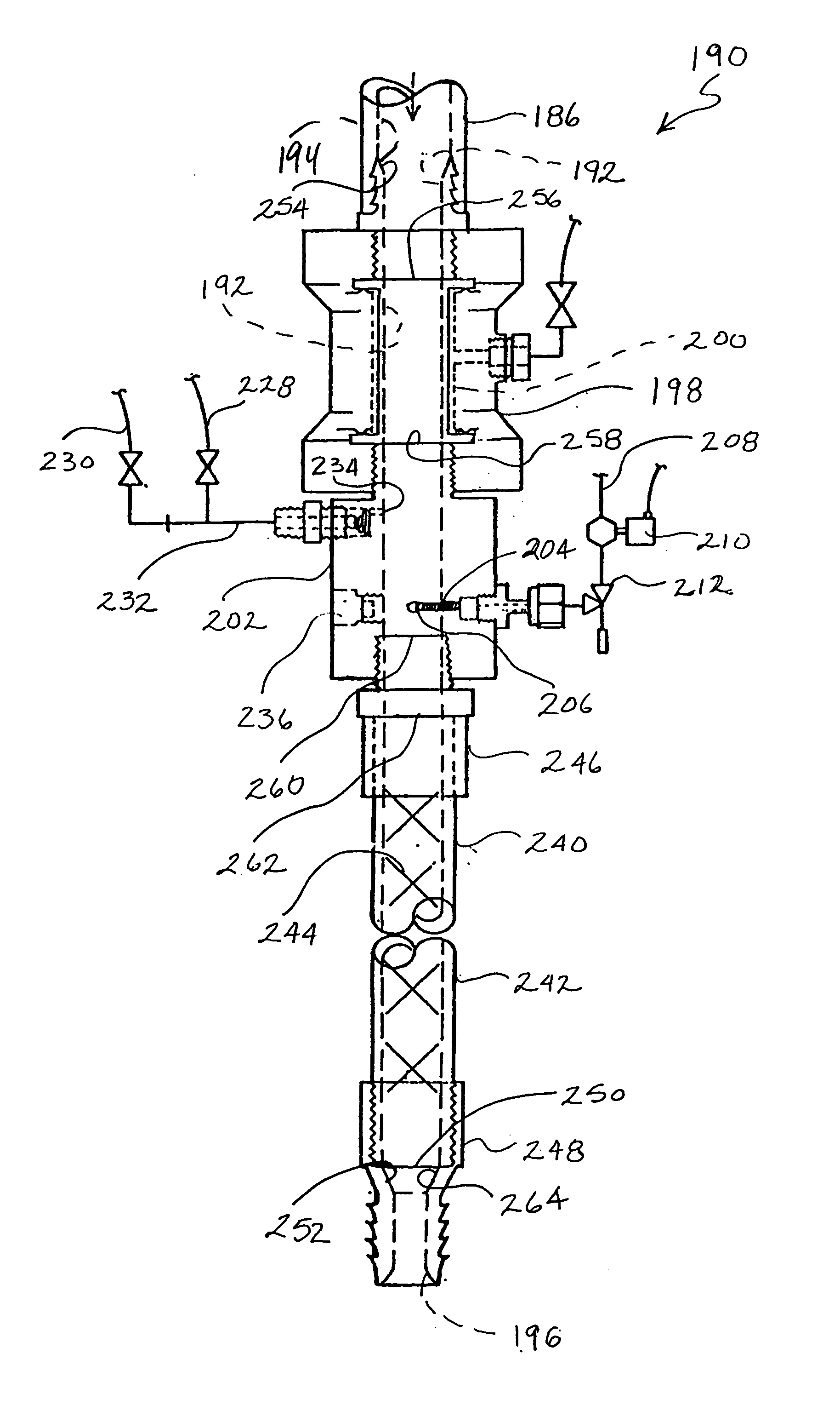
[0012] The above-listed objects are met or exceeded by the present continuous slurry dispenser apparatus, which is configured for providing clog-free, shift-type continuous operation. Particular care is taken in the design of the present apparatus for minimizing the accumulation of slurry, which in prior devices results in premature setting of the slurry and the clogging of passageways in the dispensing apparatus.
[0013] More specifically, the present invention provides an apparatus for mixing an additive into a fluid to form a settable mixture including a main fluid passageway having an inlet for receiving a supply of the fluid and an outlet for dispensing the fluid, the passageway having a longitudinal axis. The apparatus includes a control valve defining a portion of the main fluid passageway and configured for selectively controlling the flow of fluid in the passageway, an additive injector disposed in the passageway between the valve and the outlet. An emitter on the injector is disposed in close relationship with the axis and is oriented toward the outlet. A static mixer is disposed between the injector and the outlet for enhancing the uniform mixing of the additive and the fluid. Connection points between the inlet, the valve and the static mixer are configured for smooth transition of fluid and the prevention of at least one of the collection and premature setting of the mixture in the passageway.
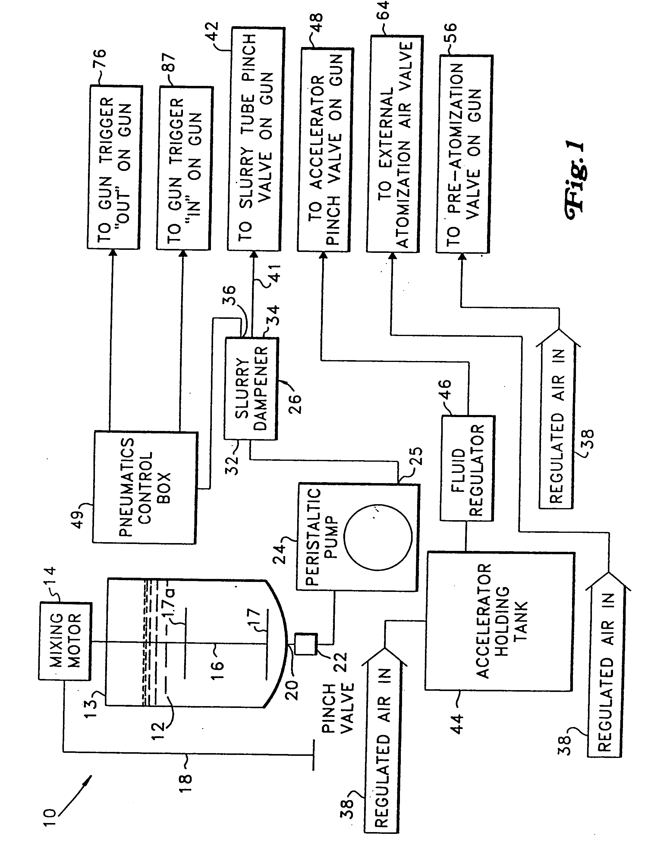
[0014] In another embodiment, a high performance slurry spray machine which features an applicator or spray gun having two points of atomization by compressed air. The first atomization point introduces compressed air into the slurry to increase its spray ability. A second atomization point is preferably located at the slurry spray outlet of the spray gun, and achieves two goals. First, the slurry is still further atomized, for a more even application. Second, the accelerant is vaporized and blended with compressed air at the second atomization point to prevent in-gun clogging while providing a more uniform distribution of accelerant in the sprayed slurry. Specially designed manifolds and outlet nozzles are provided for atomizing the slurry and for mixing the vaporized and atomized accelerant with the main slurry flow. An open-topped slurry container coupled to a positive displacement pump provides constant feed flow of this type of slurry.
[0015] Another feature of the present spray apparatus is the inclusion of a dampening device in applications where a pulsating-type pump is employed. The dampener evens out the flow pulses, and is designed to be used with the somewhat abrasive and sometimes relatively viscous plaster slurries. Pneumatically controlled pinch valves are used throughout the apparatus to prevent the clogging through plaster buildup inherent with conventional ball valves.

Problems solved by technology

Particular care is taken in the design of the present apparatus for minimizing the accumulation of slurry, which in prior devices results in premature setting of the slurry and the clogging of passageways in the dispensing apparatus.

Method used


Image

  • Continuous slurry dispenser apparatus
  • Continuous slurry dispenser apparatus
  • Continuous slurry dispenser apparatus

Examples


Embodiment Construction

[0024] Referring now to FIG. 1, the present high performance slurry spray system is generally designated 10 and is designed for spraying settable slurries, such as plaster or gypsum cement and water slurries in industrial applications. The present apparatus is particularly suitable for applying a thin coating of slurry upon a generally vertical substrate, and achieving a relatively uniform appearing and setting layer. The system 10 includes a slurry mixing and storage tank 12 suitably dimensioned for retaining a supply of slurry. In the present system, it is preferred that alpha or beta calcium sulfate hemihydrate or plaster slurry is used, however other compositions are contemplated, for example slurries containing a mixture of alpha and / or beta calcium sulfate hemihydrate and other non calcium sulfate hemihydrate slurries such as Portland cement blends (sometimes referred to as a gypsum cement), or magnesium phosphate cement formulations, depending on the application. It is also p...


PUM

PropertyMeasurementUnit
lengthaaaaaaaaaa
flow rateaaaaaaaaaa
flow rateaaaaaaaaaa

Abstract

An apparatus for mixing an additive into a fluid to form a settable mixture includes a main fluid passageway having an inlet for receiving a supply of the fluid and an outlet for dispensing the fluid, the passageway having a longitudinal axis. The apparatus includes a control valve defining a portion of the main fluid passageway and configured for selectively controlling the flow of fluid in the passageway, an additive injector disposed in the passageway and having an emitter disposed in close relationship with the axis and oriented toward the outlet. A static mixer is disposed between the injector and the outlet for enhancing the uniform mixing of the additive and the fluid. Connection points between the inlet, the valve and the static mixer are configured for smooth transition of fluid and the prevention of at least one of the collection and premature setting of the mixture.

Description

RELATED APPLICATION [0001] This application is a Continuation-in-Part of U.S. Ser. No. 09 / 918,940, filed on Jul. 31, 2001, which is a Continuation-In-Part of U.S. Ser. No. 09 / 505,455, filed on Feb. 11, 2000 and entitled “High Performance Slurry Spray Machine”, now U.S. Pat. No. 6,273,345, issued on Aug. 14, 2001.BACKGROUND OF THE INVENTION [0002] The present invention relates generally to equipment for mixing and dispensing settable slurries in which a setting agent is mixed with a settable slurry in a way that premature setting is prevented. More specifically, the present invention provides a slurry mixing and dispensing apparatus which is configured for continuously introducing a setting agent such as an accelerator into a flowing plaster slurry and thoroughly mixing the setting agent into the slurry without causing premature setting in the apparatus. [0003] Plaster slurry equipment is used for the production of cast or molded plaster products such as, but not limited to, figurine...

Claims


Application Information

Patent Timeline
Patent Type & Authority Applications(United States)
IPC IPC(8): B01F5/04B01F13/10B01F15/02B05B7/14B28C5/02B28C9/00E04F21/12F16L55/054
CPCB01F5/0451B01F15/0201B01F15/026B01F2013/108B05B7/1436F16L55/054B05B7/149B05B7/1495B28C5/026B28C9/004E04F21/12B05B7/1481B01F25/3131B01F33/83611B01F35/71805B01F35/75435B01F35/7547B01F35/7544
Inventor KALIGIAN, RAYMOND A. IIMESSER, JAMES E.LETTKEMAN, DENNISIMMORDINO, SALVATORE C.ROSS, TIMOTHY
Owner UNITED STATES GYPSUM CO
Learn More