
Flow-path constituting body

Inactive Publication Date: 2005-06-16
NIDEC SANKYO CORP
View PDF5 Cites 12 Cited by
  • Summary
  • Abstract
  • Description
  • Claims
  • Application Information

AI Technical Summary

Benefits of technology

[0007] In view of the problems described above, it is a primary object and advantage of the present invention to provide a flow-path constituting body, in which the laying work and the aligning work are easy due to its flexibility when the flow path of a fluid is constructed, and is capable of extremely easily performing the constructing work for a flow path in manufacturing. Also, it is a secondary object and advantage of the present invention to provide a flow-path constituting body which is capable of absorbing its volume variation due to the temperature variation of a fluid (liquid) while providing a sufficient flexibility, and is capable of ensuring the sealing property of the fluid.
[0008] In order to achieve the above object and advantage, according to an embodiment of the present invention, there is provided a flow-path constituting body including at least two port parts where a fluid flows in or flows out, a flow path which is in communication between the port parts, and a flexible film for forming the flow path. The flow path is constructed by using a non-bonded area defined by a bonded area of the flexible film.
[0009] In accordance with the embodiment of the present invention, the flow path is constructed of substantially only the flexible film. Therefore, its manufacturing is easy, the flexibility of the flow-path constituting body can be enhanced, and the sealing property of the flow path can be also enhanced.
[0010] Also, another flow-path constituting body in accordance with an embodiment of the present invention includes at least two port parts where a fluid flows in or flows out and a flow path which is in communication between the port parts, and at least a part of the flow path is constructed by a non-bonded area defined by a bonded area of a flexible film or a flexible film and another member.
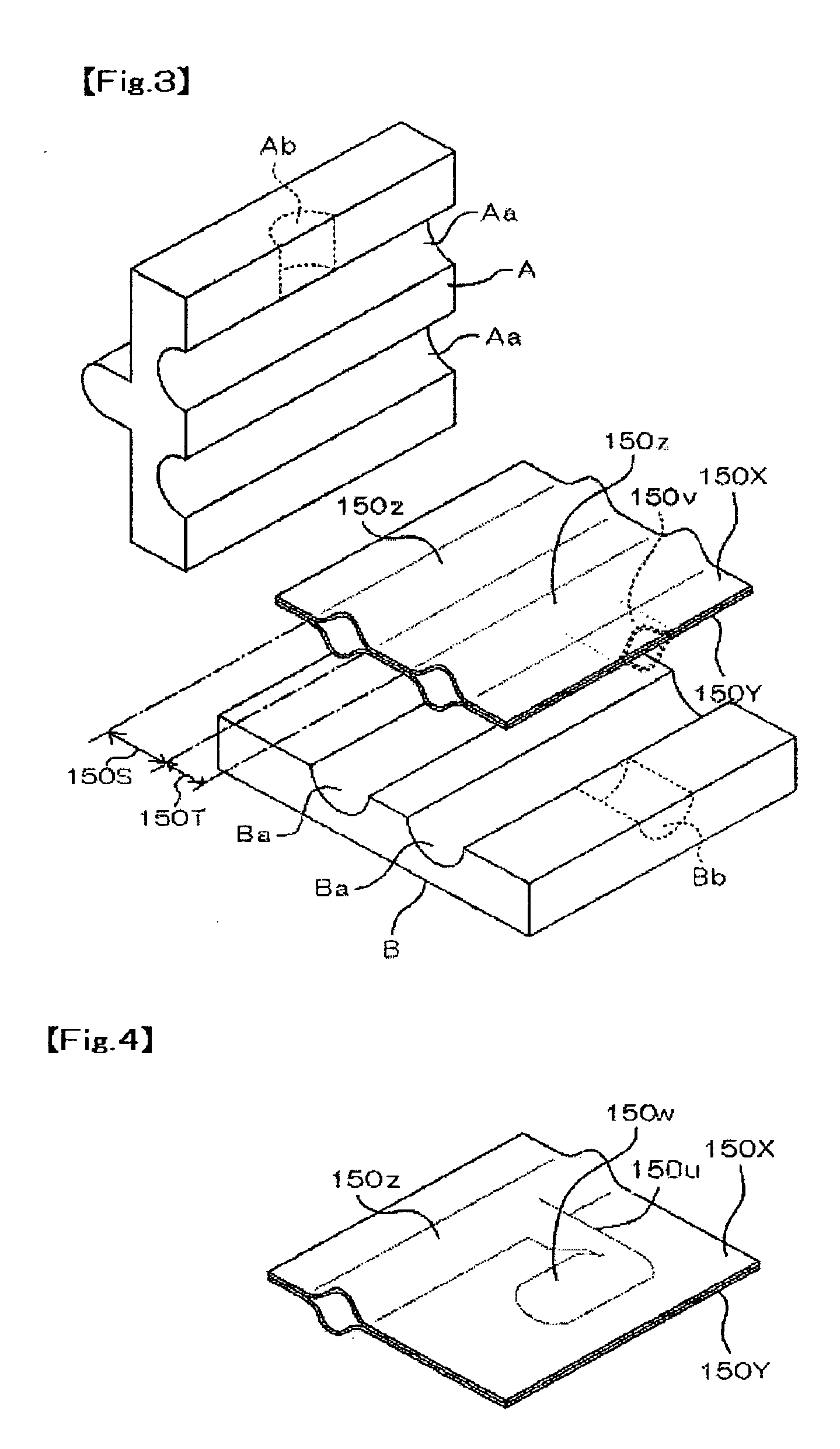
[0011] At least a part of the flow path is constructed of the non-bonded area defined by the bonded area. In this case, the flow-path constituting body may be constructed such that flexible films not less than two sheets are adhesively bonded partly to one another, one piece of flexible film is bent and folded to be adhesively bonded partly, or a flexible film and another member are adhesively bonded partly.
[0012] According to the embodiment having the construction described above, the flow path is formed so as to be in communication between the port parts and at least a part of the flow path is constructed by a non-bonded area defined by a bonded area of a flexible film or a flexible film and another member. Therefore, the flow path in an appropriate configuration and construction can be extremely easily constructed. Especially, when the flow path is constructed by the non-bonded area defined by the bonded area formed of two flexible film portions, a sufficient flexibility can be ensured and thus the laying work and the aligning work can be easily performed. Also, since the bonded area is formed by using two flexible film portions or by using a flexible film and another member, the rigidity of the bonded area can be enhanced to some extent. Therefore, since an appropriate maintenance of the flow path configuration is enabled by constructing the configuration of the flow path so as to be adapted in the system beforehand, the constructing work of the flow path can be easily performed. In addition, the flow path configuration can be extremely easily and freely formed by only appropriately designing the bonded area and the non-bonded area formed of the flexible film portions or the flexible film and the another member.

Problems solved by technology

However, in the air-cooling system described above, noise of an air-cooling fan increases as cooling performance is enhanced.
Further, since a ventilation space for cooling is not sufficiently ensured in a housing of a miniaturized computer, a sufficient cooling efficiency can not be obtained.
Therefore, a lot of tubes and connection couplings are required, which causes to increase the number of component parts and to complicate connecting operations at the time of assembling and thus time and labor are imposed for manufacturing.
Further, since a tube made of synthetic resin having flexibility is not generally provided with a gas barrier property, a coolant cannot be completely prevented from volatilizing outside at the tubes or connecting portions between the tubes and respective components.
Accordingly, a secondary chamber such as the reserve tank is required to be provided while the volatilization amount of the coolant and the degree of expansion / shrinkage of the coolant are taken into consideration and moreover a sufficient capacity is required and thus it is difficult to miniaturize the system.
However, in this case, the pipe is difficult to be bent in an appropriate shape and thus the laying work and the aligning work of piping become difficult.

Method used


Image

  • Flow-path constituting body
  • Flow-path constituting body
  • Flow-path constituting body

Examples


Embodiment Construction

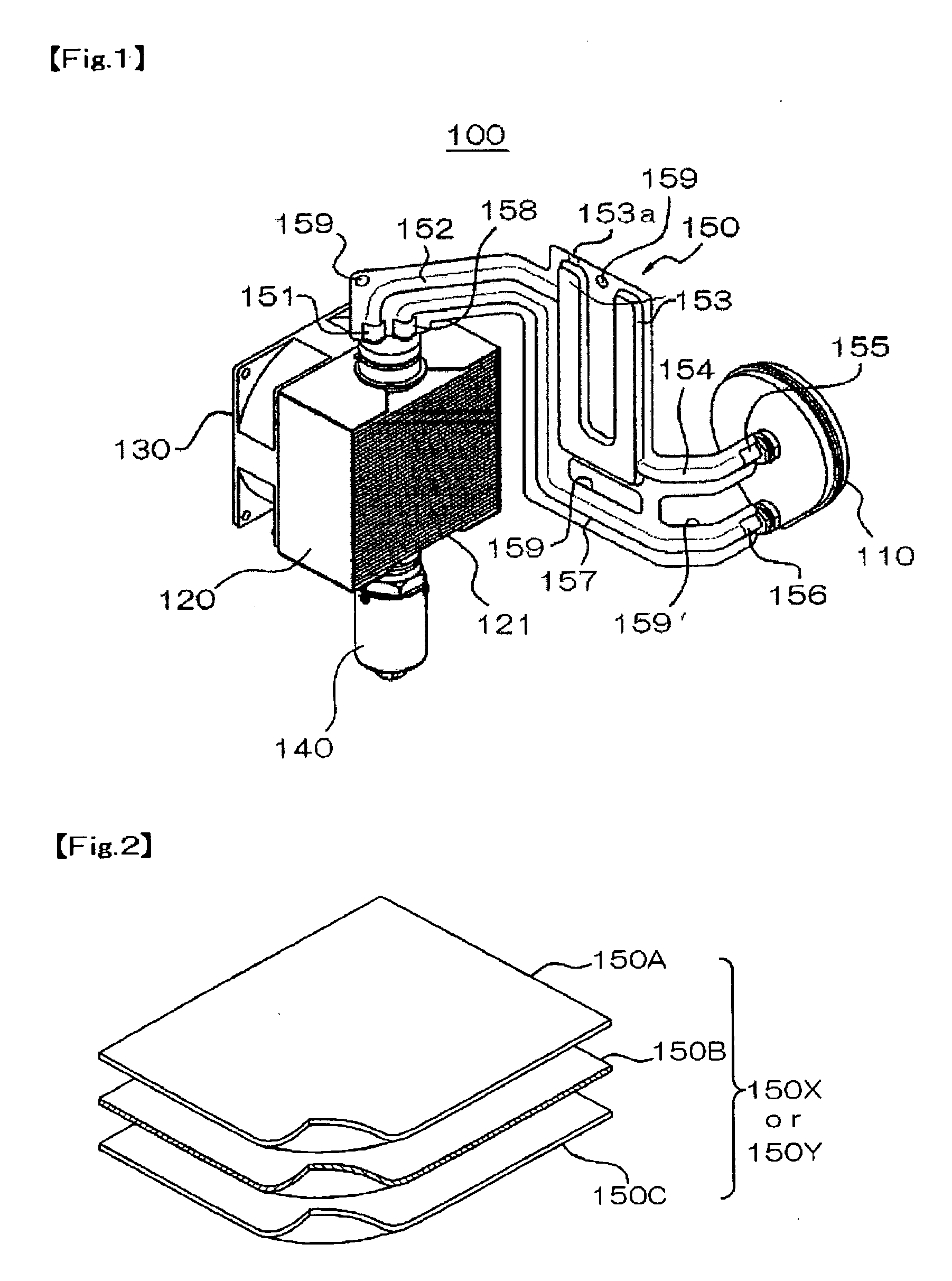
[0033] Embodiments of the present invention will be described below with reference to the accompanying drawings. Each of the embodiments described below is a flow-path constituting body which is used in a heat exchanging system including a heat receiving part, a heat radiation part and a fluid propulsion means. However, the flow-path constituting body in accordance with the present invention is not limited to the application described above. The flow-path constituting body can be widely applied to a constituting body for constructing a flow path which is arranged as a part of various systems.

[0034]FIG. 1 is a schematic construction perspective view showing an overview of a heat exchanging system 100 into which a flow-path constituting body in accordance with an embodiment of the present invention is integrated. The heat exchanging system 100 includes a heat receiving part (cooling jacket) 110, a heat radiation part (radiator) 120, a cooling fan 130 for blowing airflow to a heat rad...


PUM

PropertyMeasurementUnit
Flow rateaaaaaaaaaa
Volumeaaaaaaaaaa
Flexibilityaaaaaaaaaa

Abstract

A flow-path constituting body includes at least two port parts where a fluid flows in or flows out, a flow path that is in communication with the port parts, and a flexible film for forming the flow path. The flow path is constructed by using a non-bonded area defined by a bonded area of the flexible film. Alternatively, a flow-path constituting body includes at least two port parts where a fluid flows in or flows out and a flow path that is in communication with the port parts. At least a part of the flow path is constructed by a non-bonded area defined by a bonded area of a flexible film or a flexible film and another member.

Description

CROSS-REFERENCE TO RELATED APPLICATIONS [0001] This application claims priority to Japanese Application No. 2003-387663 filed Nov. 18, 2003, which is incorporated herein by reference. FIELD OF THE INVENTION [0002] The present invention relates to a flow-path constituting body and specifically relates to a construction of a flow-path constituting body that is suitable to cool the heating part of an electronic apparatus such as a personal computer. BACKGROUND OF THE INVENTION [0003] In recent years, the performance of a personal computer has been significantly improved and the processing speed of a CPU (Central Processing Unit) has been also rapidly improved. Therefore, the heat generating amount generated from a CPU chip and the like increases and thus an improved cooling method is required. A conventional cooling method is performed such that the heating part such as the CPU chip is fixed on a heat sink provided with fins and air-cooling is forcibly performed by sending airflow to t...

Claims


Application Information

Patent Timeline
IPC IPC(8): F28F3/00F25D9/00F28F3/14F28F21/06G06F1/20H01L23/473H05K7/20
CPCF28F3/14F28F21/065G06F1/20G06F2200/201F28F2265/26H01L2924/0002H01L23/473H01L2924/00
Inventor YOKOZAWA, MITSUOTAKASAWA, KIYOTSUGUSUGIHARA, HIROSHI
Owner NIDEC SANKYO CORP
Learn More